
Steel square
 | |
| Other names |
|
|---|---|
| Classification |
|
| Used with | |
The steel square is a tool used in
The longer wider arm is 50 millimetres (2.0 in) wide, and is called the blade; the shorter narrower arm, is 37 millimetres (1.5 in) wide, and is called the tongue. The square has many uses, including laying out common
scale. On the newer framing squares there are degree conversions for different pitches and fractional equivalents.Framing squares may also be used as
Blade and tongue
In traditional
Use
Calibration
A steel square is self-proving and self-calibrating in that you can lay out a perpendicular line, flip the square over, and determine the size and direction of the error. The error can be corrected by opening or closing the angle with a center punch.[2]
Stair framing

Stairs usually consist of three components. They are the stringer, the
Laying out a staircase requires rudimentary math. There are numerous building codes to which staircases must conform. In an open area the designer can incorporate a more desirable staircase. In a confined area this becomes more challenging. In most staircases there is one more rise than there are treads.
- The rise (vertical measurement), and the run (horizontal measurement). The stringer will rest partially on the horizontal surface.
- This is a two-by-twelvepiece of lumber. A framing square is placed on the lumber so that the desired rise and tread marks meet the edge of the board. The outline of the square is traced. The square is slid up the board until the tread is placed on the mark and the process is repeated.
- The board is cut along the dotted lines, and the top plumb cut and the bottom level cut are traced by holding the square on the opposite side.
- The stringer in this example has two pieces of tread stock. This allows for a slight overhang. There is also a space in between the boards. The bottom of the stringer must be cut to the thickness of the tread. This step is called dropping the stringer. After one stringer is cut this piece becomes the pattern that is traced onto the remaining stringers.
Roof framing
| 18" | 17" | 16" | 15" | 14" | 13" | 12" | 10" | 9" | 8" | |
|---|---|---|---|---|---|---|---|---|---|---|
| Common rafter length per foot run | 21.63" | 19.21" | 16.97" | 14.42" | ||||||
| Hip or valley rafter length per foot run | 24.74" | 22.65" | 20.78" | 18.76" | ||||||
| Difference in length of jacks 16 inch centers | 28.88" | 25.63" | 22.63" | 19.25" | ||||||
| Difference in length of jacks 24 inch centers | 43.25" | 38.44" | 33.94" | 28.88" | ||||||
| Side cut length of jack rafters | 6.69" | 7.5" | 8.5" | 10.00" | ||||||
| Side cut of hip rafter or valley rafter | 8.25" | 9.0" | 9.81" | 10.88" | ||||||
| This table shows five different types of rafter calculations and one table for marking an angle called the side cut or cheek cut. | ||||||||||
There is a table of numbers on the face side of the steel square; this is called the rafter table. The rafter table allows the carpenter to make quick calculations based on the Pythagorean theorem. The table is organized by columns that correspond to various slopes of the roof. Each column describes a different roof inclination (pitch) and contains the following information:

- Common rafter per foot of run. The common rafter connects the peak of a roof (the ridge) to the base of a roof (the plate). This number gives the length (horizontaldistance (run).
- Hip or valley rafter per foot of run. The hip or valley rafter also connects the ridge to the plate, but lies at a 45-degree angle to the common rafter. This number gives the length of the hip or valley rafter per seventeen units of run.
- Difference in lengths jacks. The jack rafters lie in the same plane as the common rafter but connect the top plate (the wall) or ridge board to the hip or valley rafter respectively. Since the hip or valley rafter meets the ridge board and the common rafter at angles of 45 degrees, the jack rafters will have varying lengths when they intersect the hip or valley. Depending on the spacing of the rafters, their lengths will vary by a constant factor—this number is the common difference.
- This angle can be cut on the fly by aligning this given number on the blade of the steel square and the twelve-inch mark on the tongue, and drawing a line along the tongue.
- Cutting hip and valley cripple rafters are all cut in a similar way.
-
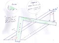
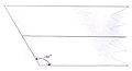
 The relationship between hip, jack and common rafters, and how they tie into the ridge and bottom plate. The rafters are fastened to the horizontal ridge board at the peak of the roof.
 -
 The side cut is the beveled angle of the hip or valley rafter that fits into the ridge board in this image.
 -
 Common and jack rafters all use twelve as the common reference to mark the plumb cut.
 -
 Hip and jack rafters use twelve as a common reference while aligning the desired pitch in the side cut column.
 -
 Hip and valley rafters use seventeen as the common reference for marking the plumb cut of a rafter.


Octagon scale
The octagon scale allows the user to inscribe an octagon inside a square, given the length of the side of the square. The markings indicate half the length of the octagon's sides, which can be set to a compass or divider. Arcs drawn from the midpoints of the square's sides will intersect the square at the vertices of the planned octagon. All that remains is to cut four triangular sections from the square.
-
 Octagon table located on the front side of the steel square.
 -
 Octagon table viewed from an aluminum square.
 -
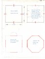 4 steps to draw Octagons.


Diagonal scale
Knee bracing is a common feature in timber framing to prevent racking under lateral loads. The diagonal scale is useful for determining the length of the a knee brace desired for a given distance from the joint between the post and beam.
-
 This is the location of the diagonal scale on the square.
 -
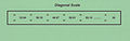 The diagonal scale gives the diagonal, or the hypotenuse, for the different legs of the triangle for which a brace is to be cut.

Calculators in roof framing

In addition to use the square tool, construction calculators are also used to verify and determine roofing calculations. Some are programmed to calculate all side cuts for hip, valley and jack regular rafters to be exactly 45° for all rafter pitches. The rafter table is expressed in inches, and the higher the numerical value of the pitch, the greater the difference between side cut angles within a given pitch. Only a level roof, or a 0 pitch will require a 45° angle side cut (cheek cut) for hip and jack rafters.
Side cut hip/valley rafter table
If a right triangle has two angles that equal 45° then the two sides are equidistant. The rafter is the hypotenuse and the legs or catheti of the triangle are the top wall plates of the structure. The side cut is located at the intersection of the given pitch column and the side cut of the hip/valley row. The regular hip/valley rafter runs at a 45° angle to the main roof and the unit of measurement is 16.97 inches of run. Regular hip/valley and jack rafters have different bevel angles within any given pitch and the angle decreases as the pitch increases.
| Legend | ||
|---|---|---|


The side cut of the hip/valley rafter = (Tangent)(12) = side cut in inches. The side cuts in the rafter table are all in a base 12. The
Side cut of jack rafters
The side cut is located at the intersection of the side cut of jack rafters row and the pitch column on the Steel square. There is a row for the difference in length of jacks, 16 and 24 inch centers on the blade. The tangents are directly proportional for both centers.

The tangent is in a base 12. The tangent x 12 = side cut of jack rafters. This corresponds to the side cut on the Steel square. The complementary angles of the arc tan are used on most angle measuring devices in construction. The tangent of hip, valley, and jack rafters are less than 1.00 in all pitches above 0°. An eighteen pitch has a side cut angle of 29.07° and a two pitch has a side cut angle of 44.56° for jack rafters. This is a variation of 15.5° between pitches.
Side cut angles versus pitch
This is a reference table for side cuts versus pitch. (only valid for 90 degrees eave angle) :
Pitch expressed in rise units / run units
Pitch 18/12 ==> 60,86 deg
Pitch 17/12 ==> 60,10 deg
Pitch 16/12 ==> 59,07 deg
Pitch 15/12 ==> 57,99 deg
Pitch 14/12 ==> 56,94 deg
Pitch 13/12 ==> 55,88 deg
Pitch 12/12 ==> 54,69 deg
Pitch 11/12 ==> 53,49 deg
Pitch 10/12 ==> 52,54 deg
Pitch 9/12 ==> 51,25 deg
Pitch 8/12 ==> 50,19 deg
Pitch 7/12 ==> 49,17 deg
Pitch 6/12 ==> 48,15 deg
Pitch 5/12 ==> 47,33 deg
Pitch 4/12 ==> 46,54 deg
Pitch 3/12 ==> 45,90 deg
Pitch 2/12 ==> 45,22 deg
Pitch 1/12 ==> 45,10 deg
Pitch 0/12 ==> 45,00 deg
Plumb cut of jack and common rafters
The plumb cut for jack and common rafters are the same angles. The level cut or seat cut is the complementary angle of the plumb cut. The notch formed at the intersection of the level and plumb cut Is commonly referred to as the bird's mouth .

Plumb cut of hip/valley rafters
The plumb cut of the hip/valley rafter is expressed in the formula. The level cut is the complementary angle or 90° minus the arc tan.

Irregular hip/valley rafters
The only Framing Square that has tables for unequal pitched roofs is the Chappell Universal Square, (patent #7,958,645). There is also a comprehensive rafter table for 6 & 8 sided polygon roofs (first time ever on a framing square). The traditional steel square's rafter table (patented April 23,1901) is limited in that it does not have tables that allow for work with unequal pitched roofs. Irregular hip/valley rafters are characterized by plan angles that are not equal or 45°. The top plates can be 90° at the outside corners or various other angles. There are numerous irregular h/v roof plans.
-
 irregular hip/valley gable roof plan.
 -
 irregular roof plan.
 -
 Intersecting irregular hip/valley gable roof plan.


Carpenter's square
In carpentry, a square is a guide for establishing right angles (90° angles) or mitre angles, usually made of metal. There are various types of square, such as speed squares, try squares and combination squares.
See also
References
Notes
- ^ Elliot, J. Hamilton (1910), Cobleigh, Rolfe (ed.), "Use of the Steel Square", Handy Farm Devices and How to Make Them, Orange Judd and Company.
- ^ "Framing Square Test & Repair". Inspectapedia. Retrieved 10 December 2021.
Bibliography
- Hodgson, Frederick T. (1880). The Carpenters' Steel Square and Its Uses. The Industrial Publication Company. LCCN 06036488.
- Siegele, H.H. (1981). The Steel Square. Sterling Publishing. ISBN 0-8069-8854-1.
- Ulrey, Harry F. (1972). Carpenters and Builders Library. Vol. 3. Theodore Audel. LCCN 74099760.
- Schuttner, Scott (1990). Basic Stairbuilding. ISBN 0-942391-44-6.
- Spence, William P. (2000). Constructing Staircases Balustrades & Landings. Sterling Publishing. ISBN 0-8069-8101-6.
- Gochnour, Chris (February 2006). "11 Essential Measuring and Woodworking Tools". Fine Woodworking (182). Taunton Press: 75.
- Lanham, Wm. The Steel Square. Bath: E. A. Lovell.
- Falconer, John (1925). Ednie, John (ed.). The Steel Square. Carpentry and Joinery. Gresham.
- Sobon, Jack (1994). Build a classic timber-framed house : planning and design, traditional materials, affordable methods. Pownal, Vt. : Storey Communications. ISBN 0882668420.
| Authority control databases: National |
|---|