
Diffraction

Diffraction is the interference or bending of waves around the corners of an obstacle or through an


In
These effects also occur when a
The amount of diffraction depends on the size of the gap. Diffraction is greatest when the size of the gap is similar to the wavelength of the wave. In this case, when the waves pass through the gap they become semi-circular.
History

The effects of diffraction of light were first carefully observed and characterized by
Mechanism

In classical physics diffraction arises because of how waves propagate; this is described by the Huygens–Fresnel principle and the principle of superposition of waves. The propagation of a wave can be visualized by considering every particle of the transmitted medium on a wavefront as a point source for a secondary spherical wave. The wave displacement at any subsequent point is the sum of these secondary waves. When waves are added together, their sum is determined by the relative phases as well as the amplitudes of the individual waves so that the summed amplitude of the waves can have any value between zero and the sum of the individual amplitudes. Hence, diffraction patterns usually have a series of maxima and minima.
In the
There are various analytical models which allow the diffracted field to be calculated, including the
It is possible to obtain a qualitative understanding of many diffraction phenomena by considering how the relative phases of the individual secondary wave sources vary, and, in particular, the conditions in which the phase difference equals half a cycle in which case waves will cancel one another out.
The simplest descriptions of diffraction are those in which the situation can be reduced to a two-dimensional problem. For water waves, this is already the case; water waves propagate only on the surface of the water. For light, we can often neglect one direction if the diffracting object extends in that direction over a distance far greater than the wavelength. In the case of light shining through small circular holes, we will have to take into account the full three-dimensional nature of the problem.
-
 Computer-generated intensity pattern formed on a screen by diffraction from a square aperture
 -
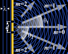 Generation of an interference pattern from two-slit diffraction
 -
 Computational model of an interference pattern from two-slit diffraction
 -
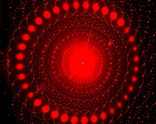 Optical diffraction pattern (laser, analogous to X-ray crystallography)
 -
![Colors seen in a spider web are partially due to diffraction, according to some analyses.[16]](//upload.wikimedia.org/wikipedia/commons/thumb/2/26/Diffraction_pattern_in_spiderweb.JPG/270px-Diffraction_pattern_in_spiderweb.JPG) Colors seen in a spider web are partially due to diffraction, according to some analyses.[16]
Colors seen in a spider web are partially due to diffraction, according to some analyses.[16]


,_(analogous_to_X-ray_crystallography).JPG)
![Colors seen in a spider web are partially due to diffraction, according to some analyses.[16]](/File:Diffraction_pattern_in_spiderweb.JPG)
Examples
The effects of diffraction are often seen in everyday life. The most striking examples of diffraction are those that involve light; for example, the closely spaced tracks on a CD or DVD act as a diffraction grating to form the familiar rainbow pattern seen when looking at a disc.


This principle can be extended to engineer a grating with a structure such that it will produce any diffraction pattern desired; the hologram on a credit card is an example.
Diffraction in the atmosphere by small particles can cause a bright ring to be visible around a bright light source like the sun or the moon.

A shadow of a solid object, using light from a compact source, shows small fringes near its edges.


The
Diffraction can occur with any kind of wave. Ocean waves diffract around jetties and other obstacles.

Sound waves can diffract around objects, which is why one can still hear someone calling even when hiding behind a tree.[18]
Diffraction can also be a concern in some technical applications; it sets a fundamental limit to the resolution of a camera, telescope, or microscope.
Other examples of diffraction are considered below.
Single-slit diffraction


.svg)
A long slit of infinitesimal width which is illuminated by light diffracts the light into a series of circular waves and the wavefront which emerges from the slit is a cylindrical wave of uniform intensity, in accordance with the Huygens–Fresnel principle.
An illuminated slit that is wider than a wavelength produces interference effects in the space downstream of the slit. Assuming that the slit behaves as though it has a large number of point sources spaced evenly across the width of the slit interference effects can be calculated. The analysis of this system is simplified if we consider light of a single wavelength. If the incident light is coherent, these sources all have the same phase. Light incident at a given point in the space downstream of the slit is made up of contributions from each of these point sources and if the relative phases of these contributions vary by or more, we may expect to find minima and maxima in the diffracted light. Such phase differences are caused by differences in the path lengths over which contributing rays reach the point from the slit.

We can find the angle at which a first minimum is obtained in the diffracted light by the following reasoning. The light from a source located at the top edge of the slit interferes destructively with a source located at the middle of the slit, when the path difference between them is equal to . Similarly, the source just below the top of the slit will interfere destructively with the source located just below the middle of the slit at the same angle. We can continue this reasoning along the entire height of the slit to conclude that the condition for destructive interference for the entire slit is the same as the condition for destructive interference between two narrow slits a distance apart that is half the width of the slit. The path difference is approximately so that the minimum intensity occurs at an angle given by


A similar argument can be used to show that if we imagine the slit to be divided into four, six, eight parts, etc., minima are obtained at angles given by


There is no such simple argument to enable us to find the maxima of the diffraction pattern. The


This analysis applies only to the
From the


When the incident angle of the light onto the slit is non-zero (which causes a change in the path length), the intensity profile in the Fraunhofer regime (i.e. far field) becomes:

![{\displaystyle I(\theta )=I_{0}\,\operatorname {sinc} ^{2}\left[{\frac {d\pi }{\lambda }}(\sin \theta \pm \sin \theta _{\text{i}})\right]}](https://wikimedia.org/api/rest_v1/media/math/render/svg/1e5854942c75d71ac603f3275ce5b18866ed637f)
The choice of plus/minus sign depends on the definition of the incident angle .


Diffraction grating
A diffraction grating is an optical component with a regular pattern. The form of the light diffracted by a grating depends on the structure of the elements and the number of elements present, but all gratings have intensity maxima at angles θm which are given by the grating equation


The light diffracted by a grating is found by summing the light diffracted from each of the elements, and is essentially a convolution of diffraction and interference patterns.
The figure shows the light diffracted by 2-element and 5-element gratings where the grating spacings are the same; it can be seen that the maxima are in the same position, but the detailed structures of the intensities are different.


Circular aperture
The far-field diffraction of a plane wave incident on a circular aperture is often referred to as the Airy disk. The variation in intensity with angle is given by


General aperture
The wave that emerges from a point source has amplitude at location that is given by the solution of the frequency domain wave equation for a point source (the Helmholtz equation),


(See del in cylindrical and spherical coordinates.) By direct substitution, the solution to this equation can be readily shown to be the scalar Green's function, which in the spherical coordinate system (and using the physics time convention ) is


This solution assumes that the delta function source is located at the origin. If the source is located at an arbitrary source point, denoted by the vector and the field point is located at the point , then we may represent the scalar Green's function (for arbitrary source location) as


Therefore, if an electric field is incident on the aperture, the field produced by this aperture distribution is given by the surface integral


where the source point in the aperture is given by the vector

In the far field, wherein the parallel rays approximation can be employed, the Green's function,


The expression for the far-zone (Fraunhofer region) field becomes

Now, since


Letting


In the far-field / Fraunhofer region, this becomes the spatial
Propagation of a laser beam
The way in which the beam profile of a
When the wave front of the emitted beam has perturbations, only the transverse coherence length (where the wave front perturbation is less than 1/4 of the wavelength) should be considered as a Gaussian beam diameter when determining the divergence of the laser beam. If the transverse coherence length in the vertical direction is higher than in horizontal, the laser beam divergence will be lower in the vertical direction than in the horizontal.
Diffraction-limited imaging

The ability of an imaging system to resolve detail is ultimately limited by


Two point sources will each produce an Airy pattern – see the photo of a binary star. As the point sources move closer together, the patterns will start to overlap, and ultimately they will merge to form a single pattern, in which case the two point sources cannot be resolved in the image. The
Thus, the larger the aperture of the lens compared to the wavelength, the finer the resolution of an imaging system. This is one reason astronomical telescopes require large objectives, and why microscope objectives require a large numerical aperture (large aperture diameter compared to working distance) in order to obtain the highest possible resolution.
Speckle patterns
The
Babinet's principle
Babinet's principle is a useful theorem stating that the diffraction pattern from an opaque body is identical to that from a hole of the same size and shape, but with differing intensities. This means that the interference conditions of a single obstruction would be the same as that of a single slit.
"Knife edge"
The knife-edge effect or knife-edge diffraction is a truncation of a portion of the incident radiation that strikes a sharp well-defined obstacle, such as a mountain range or the wall of a building. The knife-edge effect is explained by the Huygens–Fresnel principle, which states that a well-defined obstruction to an electromagnetic wave acts as a secondary source, and creates a new wavefront. This new wavefront propagates into the geometric shadow area of the obstacle.
Knife-edge diffraction is an outgrowth of the "
-
 Diffraction on a sharp metallic edge
 -
 Diffraction on a soft aperture, with a gradient of conductivity over the image width


Patterns

Several qualitative observations can be made of diffraction in general:
- The angular spacing of the features in the diffraction pattern is inversely proportional to the dimensions of the object causing the diffraction. In other words: The smaller the diffracting object, the 'wider' the resulting diffraction pattern, and vice versa. (More precisely, this is true of the sinesof the angles.)
- The diffraction angles are invariant under scaling; that is, they depend only on the ratio of the wavelength to the size of the diffracting object.
- When the diffracting object has a periodic structure, for example in a diffraction grating, the features generally become sharper. The third figure, for example, shows a comparison of a double-slit pattern with a pattern formed by five slits, both sets of slits having the same spacing, between the center of one slit and the next.
Matter wave diffraction
According to quantum theory every particle exhibits wave properties and can therefore diffract. Diffraction of electrons and neutrons is one of the powerful arguments in favor of quantum mechanics. The wavelength associated with a particle is the


Diffraction of matter waves has been observed for small particles, like electrons, neutrons, atoms, and even large molecules. The short wavelength of these matter waves makes them ideally suited to study the atomic crystal structure of solids, small molecules and proteins.
Bragg diffraction

Diffraction from a large three-dimensional periodic structure such as many thousands of atoms in a crystal is called

Bragg diffraction may be carried out using either electromagnetic radiation of very short wavelength like X-rays or matter waves like neutrons (and electrons) whose wavelength is on the order of (or much smaller than) the atomic spacing.[20] The pattern produced gives information of the separations of crystallographic planes , allowing one to deduce the crystal structure.
For completeness, Bragg diffraction is a limit for a large number of atoms with X-rays or neutrons, and is rarely valid for electron diffraction or with solid particles in the size range of less than 50 nanometers.[20]
Coherence
The description of diffraction relies on the interference of waves emanating from the same source taking different paths to the same point on a screen. In this description, the difference in phase between waves that took different paths is only dependent on the effective path length. This does not take into account the fact that waves that arrive at the screen at the same time were emitted by the source at different times. The initial phase with which the source emits waves can change over time in an unpredictable way. This means that waves emitted by the source at times that are too far apart can no longer form a constant interference pattern since the relation between their phases is no longer time independent.[21]: 919
The length over which the phase in a beam of light is correlated is called the coherence length. In order for interference to occur, the path length difference must be smaller than the coherence length. This is sometimes referred to as spectral coherence, as it is related to the presence of different frequency components in the wave. In the case of light emitted by an atomic transition, the coherence length is related to the lifetime of the excited state from which the atom made its transition.[22]: 71–74 [23]: 314–316
If waves are emitted from an extended source, this can lead to incoherence in the transversal direction. When looking at a cross section of a beam of light, the length over which the phase is correlated is called the transverse coherence length. In the case of Young's double-slit experiment, this would mean that if the transverse coherence length is smaller than the spacing between the two slits, the resulting pattern on a screen would look like two single-slit diffraction patterns.[22]: 74–79
In the case of particles like electrons, neutrons, and atoms, the coherence length is related to the spatial extent of the wave function that describes the particle.[24]: 107
Applications
Diffraction before destruction
A new way to image single biological particles has emerged since the 2010s, utilising the bright X-rays generated by X-ray free-electron lasers. These femtosecond-duration pulses will allow for the (potential) imaging of single biological macromolecules. Due to these short pulses, radiation damage can be outrun, and diffraction patterns of single biological macromolecules will be able to be obtained.[25][26]
See also
- Angle-sensitive pixel
- Atmospheric diffraction
- Brocken spectre
- Cloud iridescence
- Coherent diffraction imaging
- Diffraction from slits
- Diffraction spike
- Diffraction vs. interference
- Diffractive solar sail
- Diffractometer
- Dynamical theory of diffraction
- Electron diffraction
- Fraunhofer diffraction
- Fresnel imager
- Fresnel number
- Fresnel zone
- Point spread function
- Powder diffraction
- Quasioptics
- Refraction
- Reflection
- Schaefer–Bergmann diffraction
- Thinned-array curse
- X-ray scattering techniques
References
- ^ Francesco Maria Grimaldi, Physico mathesis de lumine, coloribus, et iride, aliisque annexis libri duo (Bologna ("Bonomia"), Italy: Vittorio Bonati, 1665), page 2 Archived 2016-12-01 at the Wayback Machine:
Original : Nobis alius quartus modus illuxit, quem nunc proponimus, vocamusque; diffractionem, quia advertimus lumen aliquando diffringi, hoc est partes eius multiplici dissectione separatas per idem tamen medium in diversa ulterius procedere, eo modo, quem mox declarabimus.
Translation : It has illuminated for us another, fourth way, which we now make known and call "diffraction" [i.e., shattering], because we sometimes observe light break up; that is, that parts of the compound [i.e., the beam of light], separated by division, advance farther through the medium but in different [directions], as we will soon show.
- ^ Cajori, Florian "A History of Physics in its Elementary Branches, including the evolution of physical laboratories." Archived 2016-12-01 at the Wayback Machine MacMillan Company, New York 1899
- ^ Wireless Communications: Principles and Practice, Prentice Hall communications engineering and emerging technologies series, T. S. Rappaport, Prentice Hall, 2002 pg 126
- ISBN 978-1-4899-0148-4. Retrieved 7 January 2023.
- ISBN 9780122274107.
- S2CID 5918772.
- ^ Francesco Maria Grimaldi, Physico-mathesis de lumine, coloribus, et iride, aliisque adnexis … [The physical mathematics of light, color, and the rainbow, and other things appended …] (Bologna ("Bonomia"), (Italy): Vittorio Bonati, 1665), pp. 1–11 Archived 2016-12-01 at the Wayback Machine: "Propositio I. Lumen propagatur seu diffunditur non solum directe, refracte, ac reflexe, sed etiam alio quodam quarto modo, diffracte." (Proposition 1. Light propagates or spreads not only in a straight line, by refraction, and by reflection, but also by a somewhat different fourth way: by diffraction.) On p. 187, Grimaldi also discusses the interference of light from two sources: "Propositio XXII. Lumen aliquando per sui communicationem reddit obscuriorem superficiem corporis aliunde, ac prius illustratam." (Proposition 22. Sometimes light, as a result of its transmission, renders dark a body's surface, [which had been] previously illuminated by another [source].)
- ^ Jean Louis Aubert (1760). Memoires pour l'histoire des sciences et des beaux arts. Paris: Impr. de S. A. S.; Chez E. Ganeau. pp. 149.
grimaldi diffraction 0–1800.
- ^ Sir David Brewster (1831). A Treatise on Optics. London: Longman, Rees, Orme, Brown & Green and John Taylor. pp. 95.
- ^ Letter from James Gregory to John Collins, dated 13 May 1673. Reprinted in: Correspondence of Scientific Men of the Seventeenth Century …, ed. Stephen Jordan Rigaud (Oxford, England: Oxford University Press, 1841), vol. 2, pp. 251–255, especially p. 254 Archived 2016-12-01 at the Wayback Machine.
- S2CID 110408369.. (Note: This lecture was presented before the Royal Society on 24 November 1803.)
- ^ Fresnel, Augustin-Jean (1816), "Mémoire sur la diffraction de la lumière" ("Memoir on the diffraction of light"), Annales de Chimie et de Physique, vol. 1, pp. 239–81 (March 1816); reprinted as "Deuxième Mémoire…" ("Second Memoir…") in Oeuvres complètes d'Augustin Fresnel, vol. 1 (Paris: Imprimerie Impériale, 1866), pp. 89–122. (Revision of the "First Memoir" submitted on 15 October 1815.)
- ^ Fresnel, Augustin-Jean (1818), "Mémoire sur la diffraction de la lumière" ("Memoir on the diffraction of light"), deposited 29 July 1818, "crowned" 15 March 1819, published in Mémoires de l'Académie Royale des Sciences de l'Institut de France, vol. V (for 1821 & 1822, printed 1826), pp. 339–475; reprinted in Oeuvres complètes d'Augustin Fresnel, vol. 1 (Paris: Imprimerie Impériale, 1866), pp. 247–364; partly translated as "Fresnel's prize memoir on the diffraction of light", in H. Crew (ed.), The Wave Theory of Light: Memoirs by Huygens, Young and Fresnel, American Book Company, 1900, pp. 81–144. (First published, as extracts only, in Annales de Chimie et de Physique, vol. 11 (1819), pp. 246–96, 337–78.)
- ^ Christiaan Huygens, Traité de la lumiere … Archived 2016-06-16 at the Wayback Machine (Leiden, Netherlands: Pieter van der Aa, 1690), Chapter 1. From p. 15 Archived 2016-12-01 at the Wayback Machine: "J'ay donc monstré de quelle façon l'on peut concevoir que la lumiere s'etend successivement par des ondes spheriques, … " (I have thus shown in what manner one can imagine that light propagates successively by spherical waves, … ) (Note: Huygens published his Traité in 1690; however, in the preface to his book, Huygens states that in 1678 he first communicated his book to the French Royal Academy of Sciences.)
- ^ Baker, B.B. & Copson, E.T. (1939), The Mathematical Theory of Huygens' Principle, Oxford, pp. 36–40.
- ^ Dietrich Zawischa. "Optical effects on spider webs". Retrieved 21 September 2007.
- ^ Arumugam, Nadia (9 September 2013). "Food Explainer: Why Is Some Deli Meat Iridescent?". Slate. The Slate Group. Archived from the original on 10 September 2013. Retrieved 9 September 2013.
- ^
Andrew Norton (2000). Dynamic fields and waves of physics. CRC Press. p. 102. ISBN 978-0-7503-0719-2.
- .
- ^ ISBN 0-444-10791-6
- ISBN 978-0-471-23231-5
- ^ ISBN 978-0-486-65957-2.
- ISBN 978-0-8053-8566-3.
- ISBN 978-0-521-45373-8. Archivedfrom the original on 16 July 2017.
- S2CID 4300920.
- PMID 24914146.
External links
- The Feynman Lectures on Physics Vol. I Ch. 30: Diffraction
- "Scattering and diffraction". Crystallography. International Union of Crystallography.
- Using a cd as a diffraction grating at YouTube
| National | |
|---|---|
| Other | |