
Search results
There is a page named "File:Sine voltage.svg" on Wikipedia
 DescriptionSine voltage.svg Deutsch: Kenngrößen an sinusförmiger Wechselspannung: 1 = Amplitude, 2 = Spitze-Spitze-Wert, 3 = Effektivwert, 4 = Periodendauer...(600 × 600 (3 KB)) - 08:13, 23 January 2023
 Derivative of Image:Sinus amplitude.svg. Other language neutral version: Image:Sine_voltage.svg English...(575 × 215 (13 KB)) - 11:46, 21 September 2021
 520×332× (9551 bytes) SVG conversion of [[:Image:Sine wave.png]] Sine wave with effective value The solid line represents the sine function, with the ordinate...(520 × 332 (9 KB)) - 06:34, 18 December 2022
 DescriptionSine wave voltages.svg English: Graph of a sine wave voltage versus time (in degrees of angle) with RMS, peak, and peak-to-peak marked. Date...(530 × 332 (19 KB)) - 00:37, 18 November 2023
 A voltage squaring circuit and analog to digital converter. ( ) Author Pakos, Paul Edward Title A voltage squaring circuit and analog to digital converter...(1,268 × 1,666 (3.41 MB)) - 19:08, 17 August 2024
 File:Sinus-spannung.gif (category Sine function)sinusfoermigen Wechselspannung.png (Markierungen selbst erstellt) Author Stefan Riepl (Quark48) Other versions Derivative works of this file: Sine voltage.svg...(350 × 300 (4 KB)) - 20:50, 18 January 2021
 File:Liniendiagramm einer Periode einer sinusfoermigen Wechselspannung.png (category Sine function)not inferior. File:Liniendiagramm einer Periode einer sinusfoermigen Wechselspannung.png → File:Sine voltage.svg For more information, see Help:SVG....(270 × 206 (2 KB)) - 20:50, 18 January 2021
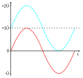 Villard Schaltung. Rot: Eingangsspannung, Türkis: Ausgangsspannung Date 25 June 2010 Source Own work Author Wdwd, Based in Parts on File:Sine voltage.svg...(330 × 310 (5 KB)) - 12:26, 2 December 2020
 DescriptionVoltage graph cs.svg Graph illustrates some mostly used terms describing the sine wave. Can translate to English or whatever. Date 10 April...(301 × 195 (13 KB)) - 02:55, 25 September 2020
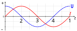 DescriptionLC circuit voltage current lapse.svg English: voltage- and current lapse at a LC circuit Deutsch: Strom- und Spannungsverlauf eines Schwingkreises...(600 × 240 (24 KB)) - 04:38, 16 September 2020
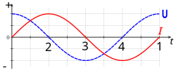 DescriptionLC circuit voltage and current lapse.svg English: voltage- and current lapse at LC circuit Deutsch: Strom- und Spannungsverlauf eines Schwingkreises...(600 × 240 (24 KB)) - 05:17, 16 October 2020
 DescriptionAc voltages max-ef-avg.svg This graph compares the maximal, effective and average voltages by the harmonical (sine) signal. Date 9 April 2007...(194 × 120 (22 KB)) - 15:52, 30 October 2023
 DescriptionDC voltage profile of B6 three-phase full-wave rectifier.jpg English: DC voltage profile of a B6 Six-pulse bridge circuit at 3 x 230 V Deutsch:...(3,416 × 2,182 (1.28 MB)) - 04:17, 2 May 2024
 DescriptionLine levels.svg English: Graph of sine waves at reference and line levels with RMS, peak, and peak-to-peak voltages marked Русский: Графики...(512 × 321 (8 KB)) - 21:53, 18 August 2024
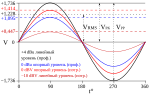 DescriptionLine levels-ru.svg English: Graph of sine waves at reference and line levels with RMS, peak, and peak-to-peak voltages marked Русский: Графики...(723 × 457 (3 KB)) - 12:15, 15 April 2021
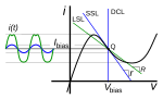 DescriptionNegative resistance oscillator load lines.svg English: Graph of the current-voltage curve of a negative resistance oscillator| showing load...(948 × 569 (25 KB)) - 16:07, 20 October 2020
 resistance such as a magnetron tube, tunnel diode, or Gunn diode to generate a sine wave signal. It consists of a resonant circuit, such as a tuned circuit,...(992 × 854 (18 KB)) - 04:10, 28 August 2023
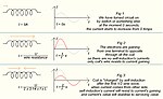 wiring. Let's consider more close: What influences to current's value if voltage is constant? -Due to Ohm's law - resistance. What forms resistance in the...(665 × 410 (87 KB)) - 13:17, 24 March 2024


