
Flying-spot scanner

A flying-spot scanner (FSS) uses a scanning source of a spot of light, such as a high-resolution, high-light-output, low-persistence
Basic principle
In the case of the CRT-based scanner, as an electron beam is drawn across the face of the CRT it creates a scan that has the correct number of lines and aspect ratio for the format of the signal. The image of this scan is focused with a lens onto the film frame. Its light passes through the image being scanned and is converted to a proportional electrical signal by photomultiplier tube(s), one for each color (red, green, blue), that detects the variations in intensity of the beam spot as it scans across the film, and are converted to proportional electrical signals, one for each of the color channels.
Telecines that use a monochrome CRT as the light source can be referred to as flying-spot scanners. The advantage of the FSS technique is that as colour analysis is done after scanning; simple dichroics may be used to split the light to each photomultiplier —and there are no registration errors, as would have been introduced by early electronic cameras.
Early use

.jpg)
Historically, flying-spot scanners were also used as primitive live-action studio cameras at the dawn of
A projector equipped with a spinning perforatedDuMont Vitascan
Flying-spot scanner technology was later implemented by DuMont Laboratories in the Vitascan color television system, released in 1956. Vitascan produced NTSC color video using a camera that acted in reverse by housing the flying-spot CRT which was projected through the camera's lens and illuminated the subject in a special light-tight studio. The light from the CRT camera was then picked up by special "scoops" housing 4 photomultiplier tubes (2 for red, 1 for green, and 1 for blue), which then would provide video of the talent in the studio. Unlike earlier FSS systems that relied on the studio being entirely darkened, Vitascan used a special strobe light would illuminate the studio for the talent's convenience, and would turn on during the photomultiplier scoop's blanking interval pulses, so as not to interfere with the scanning.
Broadcast use
Flying-spot scanners were used to scan both
See also
- Frank Gray (researcher)
- History of television
- Electronic Video Recording
- FOSDIC, a flying spot scanner used to digitize U.S. Census forms
- Cintel maker of film flying-spot scanners
- Spirit DataCine CCD Scanner
Photo gallery
-
 Mechanical Flying spot scanner 1931
 -
 Mechanical Flying spot scanner television studio 1931
 -
 Early Television System Diagram
 -
 Cathode ray Tube
 -
 Braun Cathode ray Tube from 1921
 -
 Photo Multiplier Tube And Scintillator
 -
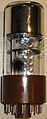 Photo Multiplier Tube
 -
 Photo Multiplier Tube


References
- ^ "Flying Spot Scanner TV Camera". earlytelevision.org.
- ^ Knox McIlwain and Charles Earle Dean (1956). Principles of Color Television. Wiley.
- ^ radiomuseum.org, Slide scanner
- ^ NASA, Visual simulation image generation using a flying-spot scanner
- ^ earlytelevision.org, cathode ray tube Rank Cintel
- ^ Bosch Fernseh, radiomuseum.org, Flying-spot scanner, 1967
- doi:10.5594/J00101.
External links
- Science Newsletter, April 16, 1927 (reproduced at Science News Online) "How New Television Process Works" with Gray's flying-spot scanner innovation