Anschütz & Co. in Kiel, to mass produce gyrocompasses; the company is today Raytheon Anschütz GmbH.[7] The gyrocompass was an important invention for nautical navigation because it allowed accurate determination of a vessel’s location at all times regardless of the vessel’s motion, the weather and the amount of steel used in the construction of the ship.[8]
In the United States, Elmer Ambrose Sperry produced a workable gyrocompass system (1908: U.S. patent 1,242,065), and founded the Sperry Gyroscope Company. The unit was adopted by the U.S. Navy (1911[3]), and played a major role in World War I. The Navy also began using Sperry's "Metal Mike": the first gyroscope-guided autopilot steering system. In the following decades, these and other Sperry devices were adopted by steamships such as the RMS Queen Mary, airplanes, and the warships of World War II. After his death in 1930, the Navy named the USS Sperry after him.
Meanwhile, in 1913, C. Plath (a Hamburg, Germany-based manufacturer of navigational equipment including sextants and magnetic compasses) developed the first gyrocompass to be installed on a commercial vessel. C. Plath sold many gyrocompasses to the Weems’ School for Navigation in Annapolis, MD, and soon the founders of each organization formed an alliance and became Weems & Plath.[9]
The 1889 Dumoulin-Krebs gyroscope
Before the success of the gyrocompass, several attempts had been made in Europe to use a gyroscope instead. By 1880,
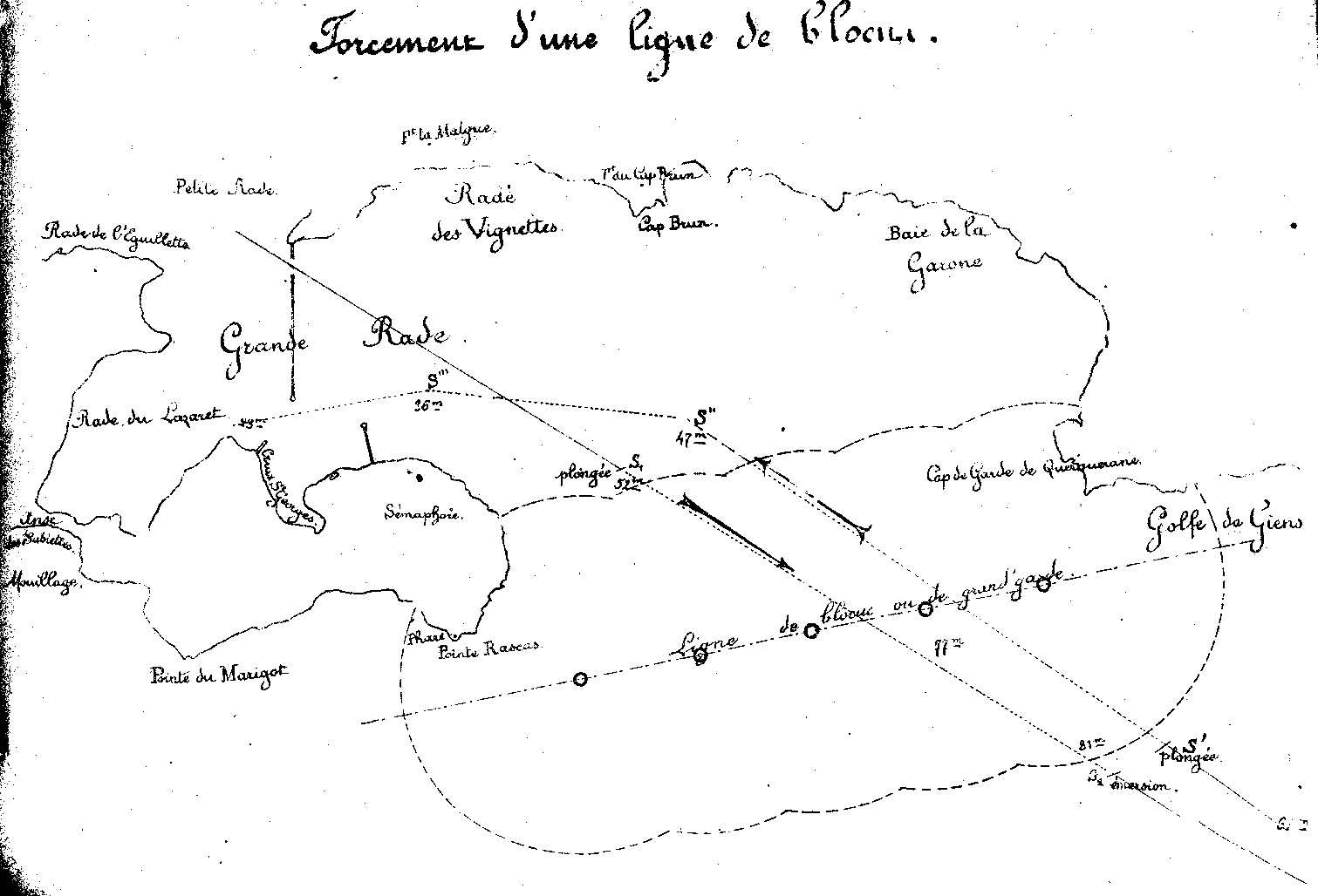
Arthur Krebs adapted an electric motor to the Dumoulin-Froment marine gyroscope, for the French Navy. That gave the Gymnote submarine the ability to keep a straight line while underwater for several hours, and it allowed her to force a naval block
in 1890.
In 1923 Max Schuler published his paper containing his observation that if a gyrocompass possessed Schuler tuning such that it had an oscillation period of 84.4 minutes (which is the orbital period of a notional satellite orbiting around the Earth at sea level), then it could be rendered insensitive to lateral motion and maintain directional stability.[10]
Operation
A
gimbals so that its axis is free to orient itself in any way.[3] When it is spun up to speed with its axis pointing in some direction, due to the law of conservation of angular momentum, such a wheel will normally maintain its original orientation to a fixed point in outer space (not to a fixed point on Earth). Since the Earth rotates, it appears to a stationary observer on Earth that a gyroscope's axis is completing a full rotation once every 24 hours.[note 1] Such a rotating gyroscope is used for navigation in some cases, for example on aircraft, where it is known as heading indicator or directional gyro, but cannot ordinarily be used for long-term marine navigation. The crucial additional ingredient needed to turn a gyroscope into a gyrocompass, so it would automatically position to true north,[2][3] is some mechanism that results in an application of torque
whenever the compass's axis is not pointing north.
One method uses
line of longitude. Once the axis points toward the celestial pole, it will appear to be stationary and won't experience any more frictional forces. This is because true north (or true south) is the only direction for which the gyroscope can remain on the surface of the earth and not be required to change. This axis orientation is considered to be a point of minimum potential energy
.
Another, more practical, method is to use weights to force the axis of the compass to remain horizontal (perpendicular to the direction of the center of the Earth), but otherwise allow it to rotate freely within the horizontal plane.[2][3] In this case, gravity will apply a torque forcing the compass's axis toward true north. Because the weights will confine the compass's axis to be horizontal with respect to the Earth's surface, the axis can never align with the Earth's axis (except on the Equator) and must realign itself as the Earth rotates. But with respect to the Earth's surface, the compass will appear to be stationary and pointing along the Earth's surface toward the true North Pole.
Since the gyrocompass's north-seeking function depends on the rotation around the axis of the Earth that causes
torque-induced gyroscopic precession, it will not orient itself correctly to true north if it is moved very fast in an east to west direction, thus negating the Earth's rotation. However, aircraft commonly use heading indicators or directional gyros, which are not gyrocompasses and do not align themselves to north via precession, but are periodically aligned manually to magnetic north.[11][12]
Errors
A gyrocompass is subject to certain errors. These include steaming error, where rapid changes in course, speed and
GPS
or other navigational aids feed data to the gyrocompass allowing a small computer to apply a correction.
Alternatively a design based on a
We consider a gyrocompass as a gyroscope which is free to rotate about one of its symmetry axes, also the whole rotating gyroscope is free to rotate on the horizontal plane about the local vertical. Therefore there are two independent local rotations. In addition to these rotations we consider the rotation of the Earth about its north-south (NS) axis, and we model the planet as a perfect sphere. We neglect friction and also the rotation of the Earth about the Sun.
In this case a non-rotating observer located at the center of the Earth can be approximated as being an inertial frame. We establish cartesian coordinates for such an observer (whom we name as 1-O), and the barycenter of the gyroscope is located at a distance from the center of the Earth.
First time-dependent rotation
Consider another (non-inertial) observer (the 2-O) located at the center of the Earth but rotating about the NS-axis by We establish coordinates attached to this observer as
so that the unit versor is mapped to the point . For the 2-O neither the Earth nor the barycenter of the gyroscope is moving. The rotation of 2-O relative to 1-O is performed with angular velocity . We suppose that the axis denotes points with zero longitude (the prime, or Greenwich, meridian).
Second and third fixed rotations
We now rotate about the axis, so that the -axis has the longitude of the barycenter. In this case we have
With the next rotation (about the axis of an angle , the co-latitude) we bring the axis along the local zenith (-axis) of the barycenter. This can be achieved by the following orthogonal matrix (with unit determinant)
so that the versor is mapped to the point
Constant translation
We now choose another coordinate basis whose origin is located at the barycenter of the gyroscope. This can be performed by the following translation along the zenith axis
so that the origin of the new system, is located at the point and is the radius of the Earth. Now the -axis points towards the south direction.
Fourth time-dependent rotation
Now we rotate about the zenith -axis so that the new coordinate system is attached to the structure of the gyroscope, so that for an observer at rest in this coordinate system, the gyrocompass is only rotating about its own axis of symmetry. In this case we find
The axis of symmetry of the gyrocompass is now along the -axis.
Last time-dependent rotation
The last rotation is a rotation on the axis of symmetry of the gyroscope as in
Dynamics of the system
Since the height of the gyroscope's barycenter does not change (and the origin of the coordinate system is located at this same point), its gravitational potential energy is constant. Therefore its Lagrangian corresponds to its kinetic energy only. We have
where is the mass of the gyroscope, and
is the squared inertial speed of the origin of the coordinates of the final coordinate system (i.e. the center of mass). This constant term does not affect the dynamics of the gyroscope and it can be neglected. On the other hand, the tensor of inertia is given by
and
Therefore we find
The Lagrangian can be rewritten as
where
is the part of the Lagrangian responsible for the dynamics of the system. Then, since , we find
Since the angular momentum of the gyrocompass is given by we see that the constant is the component of the angular momentum about the axis of symmetry. Furthermore, we find the equation of motion for the variable as
or
Particular case: the poles
At the poles we find and the equations of motion become
This simple solution implies that the gyroscope is uniformly rotating with constant angular velocity in both the vertical and symmetrical axis.
The general and physically relevant case
Let us suppose now that and that , that is the axis of the gyroscope is approximately along the north-south line, and let us find the parameter space (if it exists) for which the system admits stable small oscillations about this same line. If this situation occurs, the gyroscope will always be approximately aligned along the north-south line, giving direction. In this case we find
Consider the case that
and, further, we allow for fast gyro-rotations, that is
Therefore, for fast spinning rotations, implies In this case, the equations of motion further simplify to
Therefore we find small oscillations about the north-south line, as , where the angular velocity of this harmonic motion of the axis of symmetry of the gyrocompass about the north-south line is given by
which corresponds to a period for the oscillations given by
Therefore is proportional to the geometric mean of the Earth and spinning angular velocities. In order to have small oscillations we have required , so that the North is located along the right-hand-rule direction of the spinning axis, that is along the negative direction of the -axis, the axis of symmetry. As a side result, on measuring (and knowing ), one can deduce the local co-latitude
See also
Acronyms and abbreviations in avionics
Heading indicator, also known as direction indicator, a lightweight gyroscope (not a gyrocompass) used on aircraft
^"Archived copy"(PDF). Archived(PDF) from the original on 2015-06-29. Retrieved 2012-02-19.{{cite web}}: CS1 maint: archived copy as title (link) Standard 22
Anschütz Gyro Compass [sic] System: Gyro Compass [sic] Technology [sic] for over than [sic] 100 years
Trainer, Matthew (2008). "Albert Einstein's expert opinions on the Sperry vs. Anschütz gyrocompass patent dispute". World Patent Information. 30 (4): 320–325.


![{\displaystyle {\begin{aligned}{\mathcal {L}}&={\frac {1}{2}}\left[I_{1}\omega _{1}^{2}+I_{2}\left(\omega _{2}^{2}+\omega _{3}^{2}\right)\right]\\&={\frac {1}{2}}I_{1}\left({\dot {\psi }}-\Omega \sin \delta \cos \alpha \right)^{2}+{\frac {1}{2}}I_{2}\left\{\left[{\dot {\alpha }}\sin \psi +\Omega (\sin \delta \sin \alpha \cos \psi +\cos \delta \sin \psi )\right]^{2}+\left[{\dot {\alpha }}\cos \psi +\Omega (-\sin \delta \sin \alpha \sin \psi +\cos \delta \cos \psi )\right]^{2}\right\}\\&={\frac {1}{2}}I_{1}\left({\dot {\psi }}-\Omega \sin \delta \cos \alpha \right)^{2}+{\frac {1}{2}}I_{2}\left\{{\dot {\alpha }}^{2}+\Omega ^{2}\left(\cos ^{2}\delta +\sin ^{2}\alpha \sin ^{2}\delta \right)+2{\dot {\alpha }}\Omega \cos \delta \right\}\end{aligned}}}](https://wikimedia.org/api/rest_v1/media/math/render/svg/99ea7fb4d7a5a7959dd44adbf50a88c24e3c5f8c)


