
Muzzle booster
This article needs additional citations for verification. (September 2018) |

A muzzle booster or recoil booster is a device fixed to the
The muzzle booster is distinct from the muzzle brake, which is designed to use the propellant gases to reduce the recoil of the firearm. However, unlike a muzzle brake, a muzzle booster uses the pressure of the expanding gases, rather than the reaction force, and it does not alter the felt recoil of the weapon, it merely adds more energy to the operating components.
History
When
At firing, the recoil from the cartridge pushes the barrel and bolt together backwards within the gun. This movement provides the energy required to extract and eject the spent cartridge, and compresses the recoil spring to complete the cycle. The muzzle booster increased the recoil force transmitted to the barrel by directing some of the escaping gas into pushing the barrel back rather than letting it all expand outwards at the muzzle, in essence acting as an auxiliary gas-operating system, with the barrel acting the role of the operating rod. This increased the initial velocity of the barrel and bolt, providing more energy for the operation of the mechanism.[5]
Construction

A Vickers-type muzzle (or recoil) booster, the "typical" type, consists of two parts: a flared "cup" on the muzzle of the barrel, and a perforated tube around the end of the muzzle, attached to the main body of the weapon. The end of the latter is closed except for a small hole for the bullet to pass through. As the bullet exits the barrel, the expanding gases follow it into the chamber created between the cup and the shroud. As it passes through the close tolerance hole in the end of the perforated tube, it temporarily forms a blockage to further forward movement of the expanding gas from the barrel. The pressure inside the booster rises very rapidly as the gases continue to expand in the confined space (even after the bullet has cleared the hole, the gas pressure is still very high).
The cup on the muzzle of the barrel provides a large, movable surface for the gas to push against, as it exerts force equally in all directions. As the outer shroud is fixed to the main frame of the gun, and only the barrel is movable, the pressure forces the cup and barrel to the rear, acting exactly as a piston in a cylinder. As the barrel cycles to the rear, the cup passes the perforations in the outer shroud, opening an escape path for the gases, immediately lowering the pressure, both reducing the harsh impact when the barrel reaches full recoil and preventing the remaining pressure from the gases from acting as a "spring" and slowing the barrel when it begins to travel forwards again (which would only slow the rate of fire). The barrel continues to the rear on its own momentum, and actuates the operating mechanism. The resulting action can be seen as a composite of the recoil action and a
The name of "muzzle booster" can be misleading. The pressure within the muzzle shroud is exerted equally in all directions, pushing forwards on the shroud with the same force as it pushes the muzzle cup and barrel to the rear; thus, the actual felt recoil of the weapon is not increased, [6] even though the force imparted to the operating system is.
It is unlike a muzzle brake in that the muzzle booster extracts work from the pressure of the expanding gasses, while a muzzle brake relies on redirecting the reaction force of the fast moving gases at the muzzle. In fact, by trapping and slowing, and then redirecting the gases sideways, the device also called a "recoil booster" actually somewhat reduces the felt recoil of the weapon, by eliminating the reaction component of expanding gases escaping the muzzle in a forward direction.[6]
Applications
Historical
The original use of the recoil booster was to provide additional energy to move the large barrel/bolt mass on recoil operated machine guns.[7]
At the start of
The cooling jacket for all those designs also acted as the frame within which the barrel recoiled on firing, and which the fixed portion of the muzzle booster was mounted on. In 1915 an air-cooled version was created for use as a fixed aircraft gun, designated the lMG 08 (or LMG 08, traditionally with a lower case "L"). Eliminating water cooling saved a great deal of weight, but the water jacket was a crucial component of the gun, as it held the bushing which supported the muzzle end of the barrel and allowed it to recoil. Thus, the water jacket structure was retained, but was heavily perforated to allow cooling air-flow to reach the barrel, leaving more open space than metal. This much-lightened structure, resulting from just over 50% of the jacket's circumferential sheetmetal removed for its cooling slots; was strong enough to support the barrel, but not enough to handle the powerful forward counter-force created when the expanding gases in a muzzle brake forced the barrel rearwards. Thus, early versions of the lMG 08 deleted the muzzle booster, although later versions of the lMG 08, and its replacement, the lightened-receiver LMG 08/15 model which reduced the cooling barrel's diameter to just 92.5 mm, changed to a less-heavily perforated barrel shroud which could handle a muzzle booster, as it was realized that with the airflow over an aircraft-mounted machine gun, the fifty-percent-plus amount originally removed had been excessive.
The World War II-era
Modern
Recoil boosters have found a use in
and others. In certain cases, spacers can be used to allow the use of a Nielsen device-equipped suppressor on a fixed-barrel pistol.Some
-
 Rear of a suppressor with the Nielsen device protruding (completely assembled)
 -
 Retaining ring unscrewed and Nielsen device partially removed
 -
 Nielsen device completely removed and disassembled
 -
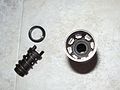 Rear of suppressor showing the rotational indexing system incorporated into some Nielsen devices


See also
Other muzzle devices
- Muzzle brake
- Flash suppressor
- Sound suppressor
- Muzzle shroud
References
- ^ Annual Reports of the Navy Department for the Fiscal Year ... U.S. Government Printing Office. 1894. p. 360.
- ^ https://youtube.com?v=A85S8u7L4j8
- ^ GB 189420627A
- ^ GB 190429423A
- ISBN 978-0-517-24234-6.
- ^ a b Weeks, John (1972). Infantry Weapons. Pan Books. p. 16.
- ISBN 978-1-4402-2482-9.
- ISBN 978-1-119-96477-3.
- ISBN 978-1-4665-8881-3.