
N-localizer
| N-localizer | ||
|---|---|---|
Specialty neurosurgery, radiation oncology | | |
| Intervention | stereotactic surgery, radiosurgery | |
| Inventor(s) | Russell A. Brown[2] | |
| ] | ||
The N-localizer
The N-localizer is integrated with the Brown-Roberts-Wells (BRW),[8] Kelly-Goerss,[9] Leksell,[10] Cosman-Roberts-Wells (CRW),[11] Micromar-ETM03B, FiMe-BlueFrame, Macom, and Adeor-Zeppelin[12] stereotactic frames and with the Gamma Knife radiosurgery system.[13]
An alternative to the N-localizer is the Sturm-Pastyr localizer that comprises three rods wherein two diagonal rods form a V-shape and a third, vertical rod is positioned midway between the two diagonal rods (Figure 3).[14] The Sturm-Pastyr localizer is integrated with the Riechert-Mundinger and Zamorano-Dujovny stereotactic frames.[15]
Compared to the N-localizer, the Sturm-Pastyr localizer is less accurate and necessitates more elaborate calculations to determine the spatial orientation of the tomographic image plane relative to the stereotactic frame.[16] In contrast to the N-localizer that does not require specification of the pixel size in a tomographic image,[17] the Sturm-Pastyr localizer requires precise specification of the pixel size.[18]
Research conducted four decades after the introduction of the N-localizer[19] and Sturm-Pastyr localizer[20] has revealed computational techniques that improve the accuracy of both localizers.
Figures
-
 Figure 1. Depiction of the N-localizer and its intersection with the tomographic image plane. (A) Side view of the N-localizer. The tomographic image plane intersects two vertical rods and one diagonal rod. (B) Tomographic image. The intersection of the tomographic image plane with the N-localizer creates two fiducial circles and one fiducial ellipse. The relative spacing between the ellipse and the two circles varies with the height at which the tomographic image plane intersects the diagonal rod.
 -
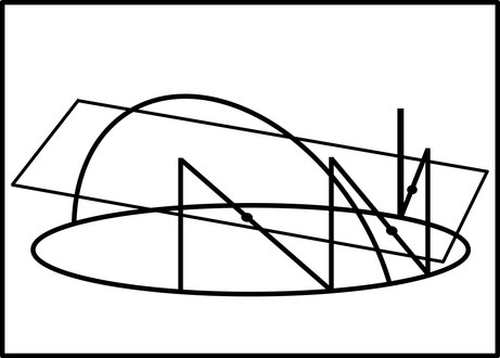 Figure 2. Depiction of three N-localizers and their intersection with the tomographic image plane. The quadrilateral represents the tomographic image plane. The oval and the arch represent the stereotactic instrument. The vertical and diagonal lines attached to the oval represent three N-localizers. The three points where the tomographic image plane intersects the diagonal rods are depicted by the dots. These points of intersection determine the spatial orientation of the tomographic image plane relative to the stereotactic frame.
 -
 Figure 3. Depiction of the Sturm-Pastyr localizer and its intersection with the tomographic image plane. (A) Side view of the Sturm-Pastyr localizer. The tomographic image plane intersects two diagonal rods and one vertical rod. (B) Tomographic image. The intersection of the tomographic image plane with the Sturm-Pastyr localizer creates two fiducial ellipses and one fiducial circle. The relative spacing between the circle and the two ellipses varies with the height at which the tomographic image plane intersects the vertical rod.


References
- S2CID 58803140.
- ^ "System Using Computed Tomography as for Selective Body Treatment". U.S. Patent 4608977. 1986.
- ISBN 978-0-12-800870-6.
- PMID 6363629.
- PMID 3329837.
- PMID 1439330.
- S2CID 58803140.
- PMID 6345727.
- PMID 7041006.
- PMID 3882889.
- S2CID 1363168.
- PMID 32670714.
- ISBN 978-1-4614-8362-5.
- S2CID 38864553.
- S2CID 58803140.
- PMID 32685325.
- PMID 2406230.
- S2CID 9196917.
- PMID 33758694.
- PMID 34660100.
Further reading
- Saleh, H; Kassas, B (2014). "Developing Stereotactic Frames for Cranial Treatment". In Benedict, SH; Schlesinger, DJ; Goetsche, SJ; Kavanagh, BD (eds.). Stereotactic Radiosurgery and Stereotactic Body Radiation Therapy. Boca Raton: CRC Press. pp. 156–159. S2CID 58555632.