
Parabolic reflector


A parabolic (or paraboloid or paraboloidal) reflector (or dish or mirror) is a
Parabolic reflectors are used to collect energy from a distant source (for example sound waves or incoming
Theory
Strictly, the three-dimensional shape of the reflector is called a paraboloid. A parabola is the two-dimensional figure. (The distinction is like that between a sphere and a circle.) However, in informal language, the word parabola and its associated adjective parabolic are often used in place of paraboloid and paraboloidal.
If a parabola is positioned in Cartesian coordinates with its vertex at the origin and its axis of symmetry along the y-axis, so the parabola opens upward, its equation is , where is its focal length. (See "Parabola#In a cartesian coordinate system".) Correspondingly, the dimensions of a symmetrical paraboloidal dish are related by the equation: , where is the focal length, is the depth of the dish (measured along the axis of symmetry from the vertex to the plane of the rim), and is the radius of the dish from the center. All units used for the radius, focal point and depth must be the same. If two of these three quantities are known, this equation can be used to calculate the third.


A more complex calculation is needed to find the diameter of the dish measured along its surface. This is sometimes called the "linear diameter", and equals the diameter of a flat, circular sheet of material, usually metal, which is the right size to be cut and bent to make the dish. Two intermediate results are useful in the calculation: (or the equivalent: ) and , where F, D, and R are defined as above. The diameter of the dish, measured along the surface, is then given by: , where means the natural logarithm of x, i.e. its logarithm to base "e".


The volume of the dish is given by where the symbols are defined as above. This can be compared with the formulae for the volumes of a


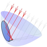
The parabolic reflector functions due to the geometric properties of the paraboloidal shape: any incoming ray that is parallel to the axis of the dish will be reflected to a central point, or "focus". (For a geometrical proof, click here.) Because many types of energy can be reflected in this way, parabolic reflectors can be used to collect and concentrate energy entering the reflector at a particular angle. Similarly, energy radiating from the focus to the dish can be transmitted outward in a beam that is parallel to the axis of the dish.
In contrast with
The precision to which a parabolic dish must be made in order to focus energy well depends on the wavelength of the energy. If the dish is wrong by a quarter of a wavelength, then the reflected energy will be wrong by a half wavelength, which means that it will interfere destructively with energy that has been reflected properly from another part of the dish. To prevent this, the dish must be made correctly to within about 1/20 of a wavelength. The wavelength range of visible light is between about 400 and 700 nanometres (nm), so in order to focus all visible light well, a reflector must be correct to within about 20 nm. For comparison, the diameter of a human hair is usually about 50,000 nm, so the required accuracy for a reflector to focus visible light is about 2500 times less than the diameter of a hair. For example, the flaw in the Hubble Space Telescope mirror (too flat by about 2,200 nm at its perimeter) caused severe spherical aberration until corrected with COSTAR.[2]
Microwaves, such as are used for satellite-TV signals, have wavelengths of the order of ten millimetres, so dishes to focus these waves can be wrong by half a millimetre or so and still perform well.
Variations
Focus-balanced reflector

It is sometimes useful if the
Scheffler reflector
The focus-balanced configuration (see above) requires the depth of the reflector dish to be greater than its focal length, so the focus is within the dish. This can lead to the focus being difficult to access. An alternative approach is exemplified by the Scheffler Reflector, named after its inventor, Wolfgang Scheffler. This is a paraboloidal mirror which is rotated about axes that pass through its centre of mass, but this does not coincide with the focus, which is outside the dish. If the reflector were a rigid paraboloid, the focus would move as the dish turns. To avoid this, the reflector is flexible, and is bent as it rotates so as to keep the focus stationary. Ideally, the reflector would be exactly paraboloidal at all times. In practice, this cannot be achieved exactly, so the Scheffler reflector is not suitable for purposes that require high accuracy. It is used in applications such as solar cooking, where sunlight has to be focused well enough to strike a cooking pot, but not to an exact point.[3]
Off-axis reflectors
A circular paraboloid is theoretically unlimited in size. Any practical reflector uses just a segment of it. Often, the segment includes the
Accurate off-axis reflectors, for use in solar furnaces and other non-critical applications, can be made quite simply by using a rotating furnace, in which the container of molten glass is offset from the axis of rotation. To make less accurate ones, suitable as satellite dishes, the shape is designed by a computer, then multiple dishes are stamped out of sheet metal.
Off-axis-reflectors heading from medium
-
 Off-axis satellite dish
 -
 The vertex of the paraboloid is below the bottom edge of the dish. The curvature of the dish is greatest near the vertex. The axis, which is aimed at the satellite, passes through the vertex and the receiver module, which is at the focus.


History
The principle of parabolic reflectors has been known since
Applications

The most common modern applications of the parabolic reflector are in

The
Parabolic reflectors are popular for use in creating optical illusions. These consist of two opposing parabolic mirrors, with an opening in the center of the top mirror. When an object is placed on the bottom mirror, the mirrors create a real image, which is a virtually identical copy of the original that appears in the opening. The quality of the image is dependent upon the precision of the optics. Some such illusions are manufactured to tolerances of millionths of an inch.
A parabolic reflector pointing upward can be formed by rotating a reflective liquid, like mercury, around a vertical axis. This makes the liquid-mirror telescope possible. The same technique is used in rotating furnaces to make solid reflectors.
Parabolic reflectors are also a popular alternative for increasing wireless signal strength. Even with simple ones, users have reported 3 dB or more gains.[14][15]
See also
- John D. Kraus
- Liquid-mirror telescope, paraboloids produced by rotation
- Parabolic antenna
- Parabolic trough
- Solar furnace
- Toroidal reflector
Footnotes
- ^ The closeness of this number to the value of "e", the base of natural logarithms, is just an accidental coincidence, but it does make a useful mnemonic.
References
- ^ Fitzpatrick, Richard (2007-07-14). "Spherical Mirrors". Farside.ph.utexas.edu. Retrieved 2012-11-08.
- ^ "Servicing Mission 1". NASA. Archived from the original on April 20, 2008. Retrieved April 26, 2008.
- ^ Administrator. "The Scheffler-Reflector". www.solare-bruecke.org.
- ISBN 90-04-11977-9.
- ISBN 3-540-20068-1.
- ^ "Archimedes' Weapon". Time Magazine. November 26, 1973. Archived from the original on October 12, 2007. Retrieved 2007-08-12.
- doi:10.1086/353176.
- doi:10.1086/355456.
- ^ Chambers, Robert (1875). A biographical dictionary of eminent Scotsmen. Oxford University. p. 175.
- ISBN 9783540765820. Retrieved 2012-11-08.
- ^ "Prehistory of Radio Astronomy". www.nrao.edu.
- ^ "ALMA Doubles its Power in New Phase of More Advanced Observations". ESO Announcement. Retrieved 11 January 2013.
- ^ Fitzpatrick, Richard (2007-07-14). "Spherical Mirrors". Farside.ph.utexas.edu. Retrieved 2012-11-08.
- ^ "Parabolic Reflector Free WiFi Booster". Do-It-Yourself Wireless Antennas Update and Wi-Fi Resource Center | WiFi Wireless Q & A. Binarywolf.com. 2009-08-26. Archived from the original on 2019-06-09. Retrieved 2012-11-08.
- ^ "Slideshow: Wi-Fi Shootout in the Desert". Wired. 2004-08-03. Retrieved 2012-11-08.
External links
- Java demonstration of a parabolic reflector
- Parabolic Reflector Antennas www.antenna-theory.com
- Animations demonstrating parabola mirror by QED
- Make Big Paraboloid Reflectors Using Plane Segments
| Authority control databases: National |
|---|