
Space Power Facility

Space Power Facility (SPF) is a NASA facility used to test spaceflight hardware under simulated launch and spaceflight conditions. The SPF is part of NASA's Neil A. Armstrong Test Facility, which in turn is part of the Glenn Research Center. The Neil A. Armstrong Test Facility and the SPF are located near Sandusky, Ohio (Oxford Township, Erie County, Ohio).
The SPF is able to simulate a spacecraft's launch environment, as well as in-space environments. NASA has developed these capabilities under one roof to optimize testing of spaceflight hardware while minimizing transportation issues. Space Power Facility has become a "One Stop Shop" to qualify flight hardware for crewed space flight. This facility provides the capability to perform the following environmental testing:
- Thermal-vacuum testing
- Reverberation acoustic testing
- Mechanical vibration testing
- Modal testing
- Electromagnetic interference and compatibility testing
Thermal-Vacuum Test Chamber
The Space Power Facility (SPF) is a vacuum chamber built by NASA in 1969. It stands 122 feet (37 m) high and 100 feet (30 m) in diameter, enclosing a bullet-shaped space. It is the world's largest thermal vacuum chamber. It was originally commissioned for nuclear-electric power studies under vacuum conditions, but was later decommissioned. It was subsequently recommissioned for use in testing spacecraft propulsion systems. Recent uses include testing the airbag landing systems for the Mars Pathfinder and the Mars Exploration Rovers, Spirit and Opportunity, under simulated Mars atmospheric conditions.
The facility was designed and constructed to test both nuclear and non-nuclear space hardware in a simulated Low-Earth-Orbiting environment. Although the facility was designed for testing nuclear hardware, only non-nuclear tests have been performed throughout its history. Some of the test programs that have been performed at the facility include high-energy experiments, rocket-fairing separation tests, Mars Lander system tests, deployable Solar Sail tests and International Space Station hardware tests.
The facility can sustain a high vacuum (10−6 torr, 130 μPa); simulate solar radiation via a 4 MW quartz heat lamp array, solar spectrum by a 400 kW arc lamp, and cold environments (−320 °F (−195.6 °C)) with a variable geometry cryogenic cold shroud.
The facility is available on a full-cost reimbursable basis to government, universities, and the private sector.
Aluminum Test Chamber
The Aluminum Test Chamber is a vacuum-tight aluminum plate vessel that is 100 feet (30 m) in diameter and 122 feet (37 m) high. Designed for an external pressure of 2.5 psi (17 kPa) and internal pressure of 5 psi (34 kPa), the chamber is constructed of Type 5083 aluminum which is a clad on the interior surface with a 1⁄8 in (3.2 mm) thick type 3003 aluminum for corrosion resistance. This material was selected because of its low neutron absorption cross-section. The floor plate and vertical shell are 1 inch (25 mm) (total) thick, while the dome shell is 1+3⁄8 in (35 mm). Welded circumferentially to the exterior surface is aluminum structural T-section members that are 3 feet (0.9 m) deep and 2 feet (0.6 m) wide. The doors of the test chamber are 50 by 50 feet (15 by 15 m) in size and have double door seals to prevent leakage. The chamber floor was designed for a load of 300 tons.
Concrete Chamber Enclosure
The concrete chamber enclosure serves not only as a radiological shield but also as a primary vacuum barrier from atmospheric pressure. 130 feet (40 m) in diameter and 150 feet (46 m) in height, the chamber was designed to withstand atmospheric pressure outside of the chamber at the same time vacuum conditions are occurring within. The concrete thickness varies from 6 to 8 feet (1.8 to 2.4 m) and contains a leak-tight steel containment barrier embedded within. The chamber's doors are 50 by 50 feet (15 by 15 m) and have inflatable seals. The space between the concrete enclosure and the aluminum test chamber is pumped down to a pressure of 20 torrs (2.7 kPa) during a test.
-
 The interior of the Space Power Facility.
 -
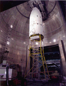
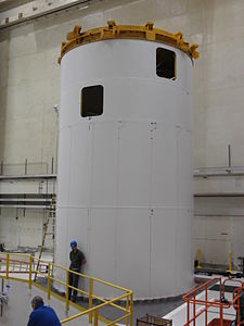
 The Centaur Standard Shroud at the Space Power Facility.
 -
 NASA's SPF Thermo-Vac chamber Scavenger Plate
 -
 NASA's SPF Thermo-Vac chamber VacCryo Pump as Seen from the Annulus Basement
 -
 NASA's SPF Thermo-Vac chamber Turbo Molecular Pumps


Brian Cox of the BBC's Human Universe filmed a rock and feather drop episode at the Space Power Facility. Below is a YouTube clip: Rock and Feather Drop at NASA's Space Power Facility
Electromagnetic Interference/Compatibility (EMI/EMC) functionality
Designed specifically as a large-scale thermal-vacuum test chamber for qualification testing of vehicles and equipment in outer-space conditions, it was discovered in the late 2000s that the unique construction of the SPF interior aluminum vacuum chamber also makes it an extremely large and electrically complex
-
 EMI mode stirrer in the Thermal-Vacuum chamber
 -
 Installation of EMI equipment in the Thermal-Vacuum Chamber


Reverberant Acoustic Test Facility
The Reverberant Acoustic Test Facility has 36 nitrogen-driven horns to simulate the high noise levels that will be experienced during a space vehicle launch and supersonic ascent conditions. The RATF is capable of an overall sound pressure level of 163 dB within a 101,500-cubic-foot (2,870 m3) chamber.
-
 The SpaceX Falcon 9 fairing was the first test article to utilize NASA's Reverberant Acoustic Test Facility (RATF).
 -
 Reverberant Acoustic Test Facility
 -
 Larry Opper in front of one of the 25 Hz horns in the RATF
 -
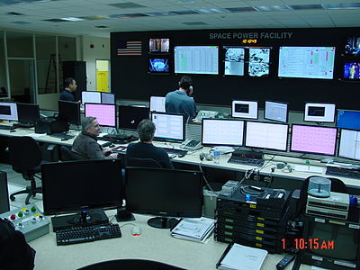 NASA's Vibro-Acoustic Control Room at the Space Power Facility


Mechanical Vibration Test Facility

The Mechanical Vibration Test Facility (MVF), is a three-axis vibration system. It will apply vibration in each of the three orthogonal axes (not simultaneously) with one direction in parallel to the Earth-launch thrust axis (X) at 5–150 Hz, 0-1.25 g-pk vertical, and 5–150 Hz 0-1.0 g-pk for the horizontal axes. Vertical, or the thrust axis, shaking is accomplished by using 16 vertical actuators manufactured by TEAM Corporation, each capable of 30,000 lbf (130 kN). The 16 vertical actuators allow for testing of up to a 75,000 lb (34,000 kg) article at the previously stated frequency and amplitude limits. Horizontal shaking is accomplished through use of 4 TEAM Corporation Horizontal Actuators. The horizontal actuators are used during Vertical testing to counteract cross axis forces and overturning moments.
-
 Mechanical Vibration Facility with the table installed
 -
 Control Accelerometer Installation
 -
 One of 16 Vertical Actuators and Spherical Coupling Assemblies for Space Power Facility's MVF
 -
 Vertical Actuator
 -
 TEAM Horizontal Actuator for the Mechanical Vibration Facility


NASA's Space Power Facility Vibro-Acoustic Construction
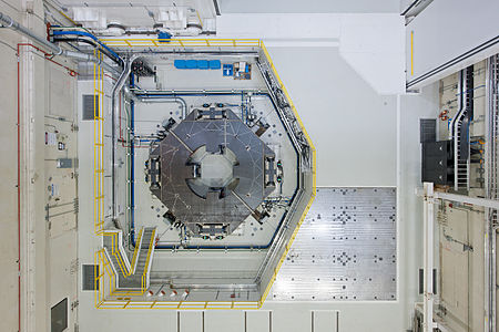
Modal Test Facility
In addition to the sine vibe table, a fixed-base Modal floor sufficient for the 20 ft (6.1 m) diameter test article is available. The fixed based Modal Test Facility is a 6 in (150 mm) thick steel floor on top of 19 ft (5.8 m) of concrete, that is tied to the earth using 50 ft (15 m) deep tensioned rock anchors.
There were over 21,000,000 pounds (9,500 t) of rock anchors, and 6,000,000 pounds (2,700 t) of concrete used in the construction of the fixed-base modal test facility and mechanical vibration test facility.
-
 The modal test facility is a 6 in (150 mm) steel plate on top of 19 ft (5.8 m) of concrete, that is then tied to the shale utilizing tensioned rock anchors that are 50 ft (15 m) long.
 -
 Mechanical Vibration Facility's Table - Modal Test (Free-Free)
 -
 Vibration Test Article - Modal Test

.JPG)

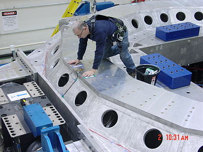
Assembly Area
The SPF Facility layout is ideal for performing multiple test programs. The facility has two large high bay areas adjacent to either side of the vacuum chamber. The advantage of having both areas available is that it allows for two complex tests to be prepared simultaneously. One test can be prepared in a high bay while another test is being conducted in the vacuum chamber. Large chamber doors provide access to the test chamber from either high bay.
NASA's Space Power Facility Vibro-Acoustic Construction
References
- ^ NIST TN-1558 - An electromagnetic evaluation of the NASA space power facility at Plum Brook Station by Koepke, Galen H.; Ladbury, John; Camell, Dennis; Coder, Jason; Hammerschmidt, Chriss; Direeen, Randall; Guerrieri, Jeff.
- ^ NASA TM—2014-218363 - Space Power Facility Reverberation Chamber Calibration Report
- ^ IEC 61000-4-21:2011 - Electromagnetic compatibility (EMC) - Part 4-21: Testing and measurement techniques - Reverberation chamber test methods
External links
- Neil Armstrong Test Facility -- official NASA website
- Skylab Shroud in Plum Brook Space Power Facility
- NASA image gallery, featuring the SPF
- Detailed facility capabilities