
Spark-gap transmitter

A spark-gap transmitter is an obsolete type of radio transmitter which generates radio waves by means of an electric spark.[1][2] Spark-gap transmitters were the first type of radio transmitter, and were the main type used during the wireless telegraphy or "spark" era, the first three decades of radio, from 1887 to the end of World War I.[3][4] German physicist Heinrich Hertz built the first experimental spark-gap transmitters in 1887, with which he proved the existence of radio waves and studied their properties.
A fundamental limitation of spark-gap transmitters is that they generate a series of brief transient pulses of radio waves called
The first practical spark gap transmitters and receivers for radiotelegraphy communication were developed by
Theory of operation
An electrically charged
Due to the inherent
A practical spark gap transmitter consists of these parts:[11][13][14][15]
- A high-voltage kilovolts to 75-100 kilovolts in powerful transmitters) to jump across the spark gap. The transformer charges the capacitor. In low-power transmitters powered by batteries this was usually an induction coil(Ruhmkorff coil).
- One or more resonant circuits (tuned circuits or tank circuits) which create radio frequency electrical oscillations when excited by the spark. A resonant circuit consists of a capacitor (in early days a type called a Leyden jar) which stores high-voltage electricity from the transformer, and a coil of wire called an inductor or tuning coil, connected together. The values of the capacitance and inductance determine the frequencyof the radio waves produced.
- The earliest spark-gap transmitters before 1897 did not have a resonant circuit; the antenna performed this function, acting as a resonator. However, this meant that the electromagnetic energy produced by the transmitter was dissipated across a wide band, thereby limiting its effective range to a few kilometers at most.
- Most spark transmitters had two resonant circuits coupled together with an air core transformer called a resonant frequency. The advantage of this circuit was that the oscillating current persisted in the antenna circuit even after the spark stopped, creating long, ringing, lightly damped waves, in which the energy was concentrated in a narrower bandwidth, creating less interference to other transmitters.
- A spark gap which acts as a voltage-controlled switch in the resonant circuit, discharging the capacitor through the coil.
- An antenna, a metal conductor such as an elevated wire, that radiates the power in the oscillating electric currents from the resonant circuit into space as radio waves.
- A telegraph key to switch the transmitter on and off to communicate messages by Morse code
Operation cycle
The transmitter works in a rapid repeating cycle in which the capacitor is charged to a high voltage by the transformer and discharged through the coil by a spark across the spark gap.[11][16] The impulsive spark excites the resonant circuit to "ring" like a bell, producing a brief oscillating current which is radiated as electromagnetic waves by the antenna.[11] The transmitter repeats this cycle at a rapid rate, so the spark appeared continuous, and the radio signal sounded like a whine or buzz in a radio receiver.

- The cycle begins when current from the transformer charges up the capacitor, storing positive electric charge on one of its plates and negative charge on the other. While the capacitor is charging the spark gap is in its nonconductive state, preventing the charge from escaping through the coil.
- When the voltage on the capacitor reaches the resistance to a very low level (usually less than one ohm). This closes the circuit between the capacitor and the coil.
- The charge on the capacitor discharges as a current through the coil and spark gap. Due to the inductance of the coil when the capacitor voltage reaches zero the current doesn't stop but keeps flowing, charging the capacitor plates with an opposite polarity, until the charge is stored in the capacitor again, on the opposite plates. Then the process repeats, with the charge flowing in the opposite direction through the coil. This continues, resulting in oscillating currents flowing rapidly back and forth between the plates of the capacitor through the coil and spark gap.
- The resonant circuit is connected to the antenna, so these oscillating currents also flow in the antenna, charging and discharging it. The current creates an oscillating electromagnetic wave; a radio wave.
- The energy in the resonant circuit is limited to the amount of energy originally stored in the capacitor. The radiated radio waves, along with the heat generated by the spark, uses up this energy, causing the oscillations to decrease quickly in amplitude to zero. When the oscillating electric current in the primary circuit has decreased to a point where it is insufficient to keep the air in the spark gap ionized, the spark stops, opening the resonant circuit, and stopping the oscillations. In a transmitter with two resonant circuits, the oscillations in the secondary circuit and antenna may continue some time after the spark has terminated. Then the transformer begins charging the capacitor again, and the whole cycle repeats.
The cycle is very rapid, taking less than a millisecond. With each spark, this cycle produces a radio signal consisting of an oscillating


The transmitter repeats this cycle rapidly, so the output is a repeating string of damped waves. This is equivalent to a radio signal
In order to transmit information with this signal, the operator turns the transmitter on and off rapidly by tapping on a switch called a telegraph key in the primary circuit of the transformer, producing sequences of short (dot) and long (dash) strings of damped waves, to spell out messages in Morse code. As long as the key is pressed the spark gap fires repetitively, creating a string of pulses of radio waves, so in a receiver the keypress sounds like a buzz; the entire Morse code message sounds like a sequence of buzzes separated by pauses. In low-power transmitters the key directly breaks the primary circuit of the supply transformer, while in high-power transmitters the key operates a heavy duty relay that breaks the primary circuit.
Charging circuit and spark rate
The circuit which charges the capacitors, along with the spark gap itself, determines the spark rate of the transmitter, the number of sparks and resulting damped wave pulses it produces per second, which determines the tone of the signal heard in the receiver. The spark rate should not be confused with the frequency of the transmitter, which is the number of sinusoidal oscillations per second in each damped wave. Since the transmitter produces one pulse of radio waves per spark, the output power of the transmitter was proportional to the spark rate, so higher rates were favored. Spark transmitters generally used one of three types of power circuits:[11][13][17]: p.359–362
Induction coil
An induction coil (Ruhmkorff coil) was used in low-power transmitters, usually less than 500 watts, often battery-powered. An induction coil is a type of transformer powered by DC, in which a vibrating arm switch contact on the coil called an interrupter repeatedly breaks the circuit that provides current to the primary winding, causing the coil to generate pulses of high voltage. When the primary current to the coil is turned on, the primary winding creates a magnetic field in the iron core which pulls the springy interrupter arm away from its contact, opening the switch and cutting off the primary current. Then the magnetic field collapses, creating a pulse of high voltage in the secondary winding, and the interrupter arm springs back to close the contact again, and the cycle repeats. Each pulse of high voltage charged up the capacitor until the spark gap fired, resulting in one spark per pulse. Interrupters were limited to low spark rates of 20–100 Hz, sounding like a low buzz in the receiver. In powerful induction coil transmitters, instead of a vibrating interrupter, a mercury turbine interrupter was used. This could break the current at rates up to several thousand hertz, and the rate could be adjusted to produce the best tone.
AC transformer
In higher power transmitters powered by AC, a transformer steps the input voltage up to the high voltage needed. The sinusoidal voltage from the transformer is applied directly to the capacitor, so the voltage on the capacitor varies from a high positive voltage, to zero, to a high negative voltage. The spark gap is adjusted so sparks only occur near the maximum voltage, at peaks of the AC sine wave, when the capacitor was fully charged. Since the AC sine wave has two peaks per cycle, ideally two sparks occurred during each cycle, so the spark rate was equal to twice the frequency of the AC power[15] (often multiple sparks occurred during the peak of each half cycle). The spark rate of transmitters powered by 50 or 60 Hz mains power was thus 100 or 120 Hz. However higher audio frequencies cut through interference better, so in many transmitters the transformer was powered by a motor–alternator set, an electric motor with its shaft turning an alternator, that produced AC at a higher frequency, usually 500 Hz, resulting in a spark rate of 1000 Hz.[15]
Quenched spark gap
The speed at which signals may be transmitted is naturally limited by the time taken for the spark to be extinguished. If, as described above, the conductive plasma does not, during the zero points of the alternating current, cool enough to extinguish the spark, a 'persistent spark' is maintained until the stored energy is dissipated, permitting practical operation only up to around 60 signals per second. If active measures are taken to break the arc (either by blowing air through the spark or by lengthening the spark gap), a much shorter "quenched spark" may be obtained. A simple quenched spark system still permits several oscillations of the capacitor circuit in the time taken for the spark to be quenched. With the spark circuit broken, the transmission frequency is solely determined by the antenna resonant circuit, which permits simpler tuning.
Rotary spark gap
In a transmitter with a "rotary" spark gap (below), the capacitor was charged by AC from a high-voltage transformer as above, and discharged by a spark gap consisting of electrodes spaced around a wheel which was spun by an electric motor, which produced sparks as they passed by a stationary electrode.[11][15] The spark rate was equal to the rotations per second times the number of spark electrodes on the wheel. It could produce spark rates up to several thousand hertz, and the rate could be adjusted by changing the speed of the motor. The rotation of the wheel was usually synchronized to the AC sine wave so the moving electrode passed by the stationary one at the peak of the sine wave, initiating the spark when the capacitor was fully charged, which produced a musical tone in the receiver. When tuned correctly in this manner, the need for external cooling or quenching airflow was eliminated, as was the loss of power directly from the charging circuit (parallel to the capacitor) through the spark.
History
The invention of the radio transmitter resulted from the convergence of two lines of research.
One was efforts by inventors to devise a system to transmit
The other was research by physicists to confirm the theory of
The division of the history of spark transmitters into the different types below follows the organization of the subject used in many wireless textbooks.[22]
Hertzian oscillators
German physicist
-
 Heinrich Hertz discovering radio waves with his spark oscillator (at rear)
 -
 Hertz's drawing of one of his spark oscillators. (A,A') antenna, (J) induction coil
 -
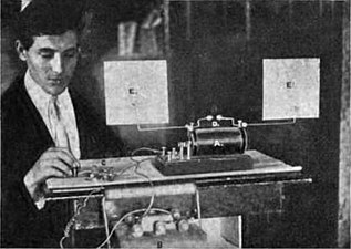 Hertzian spark oscillator, 1902. Visible are antenna consisting of 2 wires ending in metal plates (E), spark gap (D), induction coil (A), auto battery (B), and telegraph key (C).
 -
 Hertz's 450 MHz transmitter; a 26 cm dipole with spark gap at focus of a sheet metal parabolic reflector
 -
 millimeter waves; his spark oscillator (in box, right) generated 60 GHz (5 mm) waves using 3 mm metal ball resonators.
 -
 Microwave spark oscillator demonstrated by Oliver Lodge in 1894. Its 5-inch resonator ball produced waves of around 12 cm or 2.5 GHz


See circuit diagram. Hertz's transmitters consisted of a
Hertz and the first generation of physicists who built these "Hertzian oscillators", such as
To investigate the similarity between radio waves and
The high frequencies produced by Hertzian oscillators could not travel beyond the horizon. The dipole resonators also had low capacitance and couldn't store much charge, limiting their power output.[24]: p.5-9, 22 Therefore, these devices were not capable of long distance transmission; their reception range with the primitive receivers employed was typically limited to roughly 100 yards (100 meters).[24]: p.5-9, 22
Non-syntonic transmitters
I could scarcely conceive it possible that [radio's] application to useful purposes could have escaped the notice of such eminent scientists.
— Guglielmo Marconi[33]
Italian radio pioneer

He was unable to communicate beyond a half-mile until 1895, when he discovered that the range of transmission could be increased greatly by replacing one side of the Hertzian dipole antenna in his transmitter and receiver with a connection to


After failing to interest the Italian government, in 1896 Marconi moved to England, where
In 1897 Marconi started a company to produce his radio systems, which became the
Disadvantages
The primitive transmitters prior to 1897 had no
The average power output of these transmitters was low, because due to its low capacitance the antenna was a highly
A more significant drawback of the large
Syntonic transmitters

It became clear that for multiple transmitters to operate, some system of "selective signaling"
During the period 1897 to 1900 wireless researchers realized the advantages of "syntonic" or "tuned" systems, and added capacitors (Leyden jars) and inductors (coils of wire) to transmitters and receivers, to make resonant circuits (tuned circuits, or tank circuits).[36]: p. 125-136, 254–255, 259 Oliver Lodge, who had been researching electrical resonance for years,[36]: p.108-109 [44] patented the first "syntonic" transmitter and receiver in May 1897[52][57][26][36]: p.130–143 [24]: p.90-93 Lodge added an inductor (coil) between the sides of his dipole antennas, which resonated with the capacitance of the antenna to make a tuned circuit.[44][36]: p. 125-136, 254–255, 259 Although his complicated circuit did not see much practical use, Lodge's "syntonic" patent was important because it was the first to propose a radio transmitter and receiver containing resonant circuits which were tuned to resonance with each other.[44][36]: p. 125-136, 254–255, 259 In 1911 when the patent was renewed the Marconi Company was forced to buy it to protect its own syntonic system against infringement suits.[36]: p. 125-136, 254–255, 259
The resonant circuit functioned analogously to a tuning fork, storing oscillating electrical energy, increasing the Q factor of the circuit so the oscillations were less damped.[36]: p. 125-136, 254–255, 259 Another advantage was the frequency of the transmitter was no longer determined by the length of the antenna but by the resonant circuit, so it could easily be changed by adjustable taps on the coil. The antenna was brought into resonance with the tuned circuit using loading coils. The energy in each spark, and thus the power output, was no longer limited by the capacitance of the antenna but by the size of the capacitor in the resonant circuit.[17]: p.352-353, 355–358 In order to increase the power very large capacitor banks were used. The form that the resonant circuit took in practical transmitters was the inductively-coupled circuit described in the next section.
-
 Demonstration inductively coupled spark transmitter 1909, with parts labeled
 -
 Amateur inductively coupled spark transmitter and receiver, 1910. The spark gap is in glass bulb (center right) next to tuning coil, on top of box containing glass plate capacitor
 -
 Standard Marconi inductively coupled transmitter on ship 1902. Spark gap is in front of induction coil, lower right. The spiral oscillation transformer is in the wooden box on the wall above the Leyden jars.
 -
 Telefunken 25 kW long distance transmitter built 1906 at Nauen Transmitter Station, Nauen, Germany, showing large 360 Leyden jar 400 μF capacitor bank (rear) and vertical spark gaps (right)


Inductive coupling
In developing these syntonic transmitters, researchers found it impossible to achieve low damping with a single resonant circuit. A
The solution found by a number of researchers was to use two resonant circuits in the transmitter, with their coils
The first person to use resonant circuits in a radio application was
: p.352-353, 355–358In addition to Tesla's system, inductively coupled radio systems were patented by
: p.352-353, 355–358-
![Tesla's inductively coupled power transmitter (left) patented 2 September 1897[66]](//upload.wikimedia.org/wikipedia/commons/thumb/c/cf/US_Patent_645576_Nikola_Tesla_1897_System_of_transmission_of_electrical_energy.png/189px-US_Patent_645576_Nikola_Tesla_1897_System_of_transmission_of_electrical_energy.png) Tesla's inductively coupled power transmitter (left) patented 2 September 1897[66]
Tesla's inductively coupled power transmitter (left) patented 2 September 1897[66] -
![Braun's inductively coupled transmitter patented 3 November 1899[72]](//upload.wikimedia.org/wikipedia/commons/thumb/c/ce/British_patent_22%2C020-Karl_Ferdinand_Braun-filed_3_November_1899-fig._2.png/193px-British_patent_22%2C020-Karl_Ferdinand_Braun-filed_3_November_1899-fig._2.png) Braun's inductively coupled transmitter patented 3 November 1899[72]
Braun's inductively coupled transmitter patented 3 November 1899[72] -
![Stone's inductively coupled transmitter (left) and receiver (right) patented 8 February 1900[73]](//upload.wikimedia.org/wikipedia/commons/thumb/5/56/US_Patent_714756-John_Stone_Stone-Method_of_selective_electric_signaling_1900_figs_5%266.png/482px-US_Patent_714756-John_Stone_Stone-Method_of_selective_electric_signaling_1900_figs_5%266.png) Stone's inductively coupled transmitter (left) and receiver (right) patented 8 February 1900[73]
Stone's inductively coupled transmitter (left) and receiver (right) patented 8 February 1900[73] -
![Marconi's inductively coupled transmitter patented 26 April 1900.[75]](//upload.wikimedia.org/wikipedia/commons/thumb/0/0b/Spark_gap_transmitter-Marconi_patent_763772_fig_1.png/167px-Spark_gap_transmitter-Marconi_patent_763772_fig_1.png) Marconi's inductively coupled transmitter patented 26 April 1900.[75]
Marconi's inductively coupled transmitter patented 26 April 1900.[75]
![Tesla's inductively coupled power transmitter (left) patented 2 September 1897[66]](/File:US_Patent_645576_Nikola_Tesla_1897_System_of_transmission_of_electrical_energy.png)
![Braun's inductively coupled transmitter patented 3 November 1899[72]](/File:British_patent_22,020-Karl_Ferdinand_Braun-filed_3_November_1899-fig._2.png)
![Stone's inductively coupled transmitter (left) and receiver (right) patented 8 February 1900[73]](/File:US_Patent_714756-John_Stone_Stone-Method_of_selective_electric_signaling_1900_figs_5%266.png)
![Marconi's inductively coupled transmitter patented 26 April 1900.[75]](/File:Spark_gap_transmitter-Marconi_patent_763772_fig_1.png)
Marconi at first paid little attention to syntony, but by 1900 developed a radio system incorporating features from these systems,
The inductively coupled or "syntonic" spark transmitter was the first type that could communicate at intercontinental distances, and also the first that had sufficiently narrow bandwidth that interference between transmitters was reduced to a tolerable level. It became the dominant type used during the "spark" era.[33] A drawback of the plain inductively coupled transmitter was that unless the primary and secondary coils were very loosely coupled it radiated on two frequencies.[17]: p.352-353, 355–358 [79] This was remedied by the quenched-spark and rotary gap transmitters (below).
In recognition of their achievements in radio, Marconi and Braun shared the 1909
First transatlantic radio transmission


Marconi decided in 1900 to attempt transatlantic communication, which would allow him to compete with
The transmitter was built in secrecy on the coast at
Marconi's achievement received worldwide publicity, and was the final proof that radio was a practical communication technology. The scientific community at first doubted Marconi's report. Virtually all wireless experts besides Marconi believed that radio waves traveled in straight lines, so no one (including Marconi) understood how the waves had managed to propagate around the 300 mile high curve of the Earth between Britain and Newfoundland.
Knowledgeable sources today doubt whether Marconi actually received this transmission.[82][81][17]: p.387-392 Ionospheric conditions should not have allowed the signal to be received during the daytime at that range. Marconi knew the Morse code signal to be transmitted was the letter 'S' (three dots).[17]: p.387-392 He and his assistant could have mistaken atmospheric radio noise ("static") in their earphones for the clicks of the transmitter.[81][17]: p.387-392 Marconi made many subsequent transatlantic transmissions which clearly establish his priority, but reliable transatlantic communication was not achieved until 1907 with more powerful transmitters.[81]
Quenched-spark transmitters
-
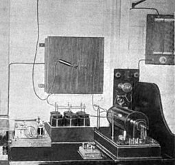
 Ship radio room with 1.5 kW Telefunken quenched-spark transmitter
 -
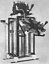 Tuned circuit of transmitter. (top) quenched gap, (center) oscillation transformer, Leyden jars
 -
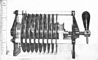 Quenched spark gap from transmitter, left. The handle turns a screw which puts pressure on the stack of cylindrical electrodes, allowing the gap widths to be adjusted.
 -
 Cross section of portion of quenched spark gap, consisting of metal disks (F) separated by thin insulating mica washers (M) to make multiple microscopic spark gaps (S) in series
 -
 A powerful quenched-spark transmitter in Australia. The 6 cylinders in front of the Leyden jars are the quenched spark gaps.


The inductively-coupled transmitter had a more complicated output waveform than the non-syntonic transmitter, due to the interaction of the two resonant circuits. The two magnetically coupled tuned circuits acted as a
This troublesome backflow of energy to the primary circuit could be prevented by extinguishing (quenching) the spark at the right instant, after all the energy from the capacitors was transferred to the antenna circuit.
In 1906, a new type of spark gap was developed by German physicist Max Wien,[87] called the series or quenched gap.[88][89][90][85] A quenched gap consisted of a stack of wide cylindrical electrodes separated by thin insulating spacer rings to create many narrow spark gaps in series,[89] of around 0.1–0.3 mm (0.004–0.01 in).[88] The wide surface area of the electrodes terminated the ionization in the gap quickly by cooling it after the current stopped. In the inductively coupled transmitter, the narrow gaps extinguished ("quenched") the spark at the first nodal point (Q) when the primary current momentarily went to zero after all the energy had been transferred to the secondary winding (see lower graph).[83] Since without the spark no current could flow in the primary circuit, this effectively uncoupled the secondary from the primary circuit, allowing the secondary resonant circuit and antenna to oscillate completely free of the primary circuit after that (until the next spark). This produced output power centered on a single frequency instead of two frequencies. It also eliminated most of the energy loss in the spark, producing very lightly damped, long "ringing" waves, with decrements of only 0.08 to 0.25[91] (a Q of 12-38) and consequently a very "pure", narrow bandwidth radio signal. Another advantage was the rapid quenching allowed the time between sparks to be reduced, allowing higher spark rates of around 1000 Hz to be used, which had a musical tone in the receiver which penetrated radio static better. The quenched gap transmitter was called the "singing spark" system.[91][88]
The German wireless giant Telefunken Co., Marconi's rival, acquired the patent rights and used the quenched spark gap in their transmitters.[90][88][85]
Rotary gap transmitters
A second type of spark gap that had a similar quenching effect[15] was the "rotary gap", invented by Tesla in 1896[92][93] and applied to radio transmitters by Reginald Fessenden and others.[17]: p.359–362 [79] It consisted of multiple electrodes equally spaced around a disk rotor spun at high speed by a motor, which created sparks as they passed by a stationary electrode.[11][48] By using the correct motor speed, the rapidly separating electrodes extinguished the spark after the energy had been transferred to the secondary.[15][11][17]: p.359–362 [79] The rotating wheel also kept the electrodes cooler, important in high-power transmitters.
-
 A typical rotary spark gap used in low-power transmitters
 -
 Small rotary spark transmitter, 1918
 -
 1 kilowatt rotary spark transmitter, 1914.
 -
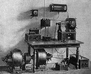
 Fessenden's 35 kW synchronous rotary spark transmitter, built 1905 at Brant Rock, Massachusetts, with which he achieved the first 2 way transatlantic communication in 1906 on 88 kHz.
 -
 US Navy 100 kW rotary gap transmitter built by Fessenden in 1913 at Arlington, Virginia. It transmitted on 113 kHz to Europe, and broadcast the US's first radio time signal.


There were two types of rotary spark transmitter:[15][17]: p.359–362 [11][79][81]
- Nonsynchronous: In the earlier rotary gaps, the motor was not synchronized with the frequency of the AC transformer, so the spark occurred at random times in the AC cycle of the voltage applied to the capacitor. The problem with this was the interval between the sparks was not constant.[17]: p.359–362 The voltage on the capacitor when a moving electrode approached the stationary electrode varied randomly between zero and the peak AC voltage. The exact time when the spark started varied depending on the gap length the spark could jump, which depended on the voltage. The resulting random phase variation of successive damped waves resulted in a signal that had a "hissing" or "rasping" sound in the receiver.[13]
- Synchronous: In this type, invented by Fessenden around 1904, the rotor was turned by a harmonics with the line frequency. The synchronous gap was said to produce a more musical, easily heard tone in the receiver, which cut through interference better.[13]
To reduce interference caused by the "noisy" signals of the burgeoning numbers of spark transmitters, the 1912 US Congress "Act to Regulate Radio Communication" required that "the logarithmic decrement per oscillation in the wave trains emitted by the transmitter shall not exceed two tenths"[48][11][94] (this is equivalent to a Q factor of 15 or greater). Virtually the only spark transmitters which could satisfy this condition were the quenched-spark and rotary gap types above,[48] and they dominated wireless telegraphy for the rest of the spark era.
Marconi's timed spark system
In 1912 in his high-power stations Marconi developed a refinement of the rotary discharger called the "timed spark" system, which generated what was probably the nearest to a
The "spark" era
The first application of radio was on ships, to keep in touch with shore, and send out a distress call if the ship were sinking.[100] The Marconi Company built a string of shore stations and in 1904 established the first Morse code distress call, the letters CQD, used until the Second International Radiotelegraphic Convention in 1906 at which SOS was agreed on. The first significant marine rescue due to radiotelegraphy was the 23 January 1909 sinking of the luxury liner RMS Republic, in which 1500 people were saved.
| Radio frequencies used by spark transmitters during the wireless telegraphy era[101] | |||
|---|---|---|---|
| Uses | Frequency (kilohertz) |
Wavelength (meters) |
Typical power range (kW) |
| Amateur | > 1500 | < 200 | 0.25 - 0.5 |
| Ships | 500, 660, 1000 | 600, 450, 300 | 1 - 10 |
| Navy | 187.5 - 500 | 1600 - 600 | 5 - 20 |
| Moderate size land stations | 187.5 - 333 | 1600 - 900 | 5 - 20 |
| Transoceanic stations | 15 - 187.5 | 20,000 - 1600 | 20 - 500 |
Spark transmitters and the
The RMS Titanic sinking 14 April 1912 increased public appreciation for the role of radio, but the loss of life brought attention to the disorganized state of the new radio industry,[106] and prompted regulation which corrected some abuses.[103] Although the Titanic radio operator's CQD distress calls summoned the RMS Carpathia which rescued 705 survivors, the rescue operation was delayed four hours because the nearest ship, the SS Californian, only a few miles away, did not hear the Titanic's call as its radio operator had gone to bed. This was held responsible for most of the 1500 deaths. Existing international regulations required all ships with more than 50 passengers to carry wireless equipment, but after the disaster subsequent regulations mandated ships have enough radio officers so that a round-the-clock radio watch could be kept. US President Taft and the public heard reports of chaos on the air the night of the disaster, with amateur stations interfering with official naval messages and passing false information.[106][107] In the US 1912 Radio Act, licenses were required for all radio transmitters, maximum damping of transmitters was limited to a decrement of 0.2 to get old noisy non-syntonic transmitters off the air, and amateurs were mainly restricted to the unused frequencies above 1.5 MHz and output power of 1 kilowatt.[94][105][15]
The largest spark transmitters were powerful transoceanic radiotelegraphy stations with input power of 100 - 300 kW.
Continuous waves
Although their damping had been reduced as much as possible, spark transmitters still produced
From the beginning, physicists knew that another type of waveform,
Beginning about 1904, continuous wave transmitters were developed using new principles, which competed with spark transmitters. Continuous waves were first generated by two short-lived technologies:[36]: p.72-79
- The resonant circuit.
- The Alexanderson alternator transmitter, developed between 1906 and 1915 by Reginald Fessenden and Ernst Alexanderson, was a huge rotating alternating current generator (alternator) driven by an electric motor at a high enough speed that it produced radio frequency current in the very low frequency range.
These transmitters, which could produce power outputs of up to one
Obsolescence
All these early technologies were superseded by the
The 1927 International Radiotelegraph Convention in Washington, D.C. saw a political battle to finally eliminate spark radio.[6] Spark transmitters were long obsolete at this point, and broadcast radio audiences and aviation authorities were complaining of the disruption to radio reception that noisy legacy marine spark transmitters were causing. But shipping interests vigorously fought a blanket prohibition on damped waves, due to the capital expenditure that would be required to replace ancient spark equipment that was still being used on older ships. The Convention prohibited licensing of new land spark transmitters after 1929.[114] Damped wave radio emission, called Class B, was banned after 1934 except for emergency use on ships.[5][114] This loophole allowed shipowners to avoid replacing spark transmitters, which were kept as emergency backup transmitters on ships through World War II.
Legacy
One legacy of spark-gap transmitters is that radio operators were regularly nicknamed "Sparky" long after the devices ceased to be used. Even today, the German verb funken, literally, "to spark", also means "to send a radio message".
The spark gap oscillator was also used in nonradio applications, continuing long after it became obsolete in radio. In the form of the
In the 1950s a Japanese toy company, Matsudaya, produced a line of cheap remote control toy trucks, boats and robots called Radicon, which used a low-power spark transmitter in the controller as an inexpensive way to produce the radio control signals.[118][119] The signals were received in the toy by a coherer receiver.
Spark gap oscillators are still used to generate high-frequency high voltage needed to initiate welding arcs in gas tungsten arc welding.[120] Powerful spark gap pulse generators are still used to simulate EMPs.
See also
References
- ^ ISBN 978-1135455514.
- ISBN 978-0122004001.
- ^ Champness, Rodney (April 2010). "The spark era - the beginning of radio". Silicon Chip Online: 92–97. Retrieved 14 March 2018.
- ^ a b Terman, Frederick Emmons (1937). Radio Engineering (2nd ed.). New York: McGraw-Hill Book Co. pp. 6–9. Retrieved September 14, 2015.
- ^ a b Individual nations enforce this prohibition in their communication laws. In the United States, Federal Communications Commission (FCC) regulations make it a felony to operate a spark transmitter: "Section 2.201: Emission, modulation, and transmission characteristics, footnote (f)". Code of Federal Regulations, Title 47, Chapter I, Subchapter A, Part 2, Subpart C. US Government Publishing Office website. 1 October 2007. Retrieved 16 March 2018.
- ^ a b Schroeder, Peter B. (1967). Contact at Sea: A History of Maritime Radio Communications. The Gregg Press. pp. 26–30.
- ISBN 978-0495386933.
- ^ ISBN 978-1316785164.
- ISBN 978-0387951508.
- ^ ISBN 978-1400854608.
- ^ a b c d e f g h i j k l m n o p Codella, Christopher F. (2016). "Spark Radio". Ham Radio History. C. F. Codella's private website. Retrieved 22 May 2018.
- ^ Fleming, John Archibald (1906). The Principles of Electric Wave Telegraphy. London: Longmans Green and Co. pp. 15–16.
- ^ a b c d e f g Kennedy, Hal (1990). "How spark transmitters work" (PDF). The history of QST Vol. 1 - Technology. American Radio Relay League. Retrieved 27 March 2018.
- ^ Morecroft, John H. (1921). Principles of Radio Communication. New York: John Wiley and Sons. pp. 275–279.
- ^ a b c d e f g h i j Hyder, Harry R. (March 1992). "The final days of ham spark" (PDF). QST. American Radio Relay League: 29–32. Retrieved 5 February 2022.
- ^ Nahin, Paul J. (2001) The Science of Radio: with MATLAB and Electronics Workbench demonstrations, 2nd Ed., p. 38-43
- ^ ISBN 978-0471783015.
- ^ ISBN 978-0387951508.
- ^ Fitzgerald, George "On the energy lost by radiation from alternating electric currents", Report of the British Association for the Advancement of Science, 1883, reprinted in Fitzgerald, George (1902). The Scientific Writings of the Late George Francis Fitzgerald. London: Hodges, Figgis, and Co. pp. 128–129.
- ISBN 978-0387951508.
- ^ Fitzgerald, George "On a method of producing electromagnetic disturbances of comparatively short wavelength", Report of the British Association for the Advancement of Science, 1883, p.405, reprinted in Fitzgerald, George (1902). The Scientific Writings of the Late George Francis Fitzgerald. London: Hodges, Figgis, and Co. p. 129.. The text in full: "This is by utilizing the alternating currents produced when an accumulator is discharged through a small resistance. It would be possible to produce waves of ten meters wavelength, or even less"
- ^ Zenneck, Jonathan Adolf Wilhelm (1915). Wireless Telegraphy. New York: McGraw Hill Book Co. pp. 173. Translated from German by A. E. Selig. Zenneck describes the Marconi, Braun, and Wien transmitters on p. 173, and the early "lineal" or Hertz oscillators on p. 41.
- ^ a b Hertz, H., "On very rapid electric oscillations", Wiedemann's Annalen, Vol. 31, p. 421, 1887 reprinted in Hertz, Heinrich (1893). Electric Waves: Being Researches on the Propagation of Electric Action with Finite Velocity Through Space. Dover Publications. pp. 29–53.
heinrich hertz .
translated to English by D. E. Jones - ^ ISBN 9780262514194.
- ^ ISBN 978-9401588553.
- ^ ISBN 978-0521835398.
- ^ ISBN 9780405060526.
- ^ ISBN 978-0786426621.
- ISBN 978-0786748549.
- ^ ISBN 978-1615303007.
- ^ Hertz, H., "On radiation", Wiedemann's Annalen, Vol. 36, December 13, 1988, p. 769, reprinted in Hertz, Heinrich (1893). Electric Waves: Being Researches on the Propagation of Electric Action with Finite Velocity Through Space. Dover Publications. pp. 172–185. translated to English by D. E. Jones
- . Retrieved January 30, 2018.
- ^ ISBN 978-0852967928.
- ISBN 978-0521835398.
- ^ a b c British patent 189612039 Marconi, Guglielmo Improvements in transmitting electrical impulses and signals, and in apparatus therefore, Applied: 2 June 1896, full specification: 2 March 1897, accepted: 2 July 1897. British patents allowed the full specification to be submitted after the application. Marconi's monopole antenna did not appear in his initial June 1896 application but in his March 1897 specification. Corresponding US patent 586193, Marconi, Guglielmo, Transmitting electrical signals, filed 7 December 1896, accepted: 13 July 1897
- ^ ISBN 978-1400857883.
- ^ ISBN 978-0471205050.
- ^ ISBN 978-0470871188.
- ISBN 978-0191533457.
- ^ Morse (1925) Radio: Beam and Broadcast, p. 24-26
- ^ Huurdeman, Anton (2003) The Worldwide History of Telecommunications, p. 212-215
- ISBN 978-0863413278.
- ^ a b c Nahin, Paul J. (2001) The Science of Radio: with MATLAB and Electronics Workbench demonstrations, 2nd Ed., p. 46
- ^
- ^ a b Marriott, Robert H. (June 1917). "United States Radio Development". Proceedings of the I.R.E. 5 (3): 179–188. Retrieved 8 March 2018.
- ^ a b c d Ashley, Hayward (1912) Wireless Telegraphy and Wireless Telephony: An understandable presentation of the science of wireless transmission of intelligence, p. 34-36
- ^ Codella, Christopher F. (2016). "Aerials, Attachments, and Audibility". Ham Radio History. Codella's private website. Retrieved 22 May 2018.
- ^ a b c d e Jansky, Cyril Methodius (1919). Principles of Radiotelegraphy. New York: McGraw-Hill Book Co. pp. 165–167.
- ^ Lee, Thomas H. 2004 The Design of CMOS Radio-Frequency Integrated Circuits, 2nd Ed., p. 6-7
- ^ Howeth, L. S. (1963). The History of Communications - Electronics in the U.S. Navy. U.S. Navy. pp. 38–39.
- ^ "Reporting the yacht races by wireless telegraph". Electrical World. 38 (15): 596–597. October 12, 1901. Retrieved 8 March 2018.
- ^ a b British patent GB189711575 Lodge, O. J. Improvements in Syntonized Telegraphy without Line Wires filed: May 10, 1897, granted: August 10, 1898
- ^ a b Ashley, Charles Grinnell; Hayward, Charles Brian (1912). Wireless telegraphy and wireless telephony: An understandable presentation of the science of wireless transmission of intelligence. American School of Correspondence. pp. 38.
selective signaling.
- ^ Kennelly, Arthur Edwin (1906). Wireless Telegraphy: An Elementary Treatise. New York: Moffat, Yard, and Co. pp. 173–180.
selective signaling.
- ^ "Crookes’s article was read very widely—and more than that, attended to and remembered—both in Europe and in the United States; there is hardly one figure important in the early days of radio who does not at some point in his memoirs or correspondence refer to the article of 1892 as having made a difference." Aitken, Hugh (2014) Syntony and Spark: The origins of radio, p. 111-116
- ^ Crookes, William (February 1, 1892). "Some Possibilities of Electricity". The Fortnightly Review. 51: 174–176. Archived from the original on September 29, 2018. Retrieved August 19, 2015.
- ^ Lodge's explanation of his syntonic radio system is in Lodge, Oliver (1900). Signaling through space without wires. London: The Electrician Publishing Co. pp. 50–58.
- ^ a b Marconi, Guglielmo (May 24, 1901). "Syntonic Wireless Telegraphy". The Electrician. Retrieved April 8, 2017.
- S2CID 51671246.
- ^ Tesla, N., "On light and other high frequency phenomena", in Thomas Cummerford Martin (1894) The Inventions, Researches and Writings of Nikola Tesla, 2nd Ed., p. 294-373
- ^ ISBN 978-1136993756.
- ISBN 978-0760710050.
- ^ ISBN 978-0471697398.
- ^ ISBN 978-0313331671.
- ^ Cheney, Margaret (2011) Tesla: Man Out Of Time, p. 96-97
- ^ a b US Patent No. 645576, Nikola Tesla, System of transmission of electrical energy, filed: 2 September 1897; granted: 20 March 1900
- ^ Wunsch, A. David (November 1998). "Misreading the Supreme Court: A Puzzling Chapter in the History of Radio". Antenna. 11 (1). Retrieved 3 December 2018.
- ISBN 978-0786426621.
- ISBN 978-0-615-24869-1.
- ^ US Patent no. 609,154 Oliver Joseph Lodge, Electric Telegraphy, filed: 1 February 1898, granted: 16 August 1898
- ^ a b c d e White, Thomas H. (1 November 2012). "Nikola Tesla: The Guy Who DIDN'T "Invent Radio"". United States Early Radio History. T. H. White's personal website. Retrieved 20 June 2018.
- ^ a b British patent no. 189922020 Karl Ferdinand Braun, Improvements in or related to telegraphy without the use of continuous wires, applied: 3 November 1899, complete specification: 30 June 1900, granted: 22 September 1900
- ^ a b US Patent no. 714,756, John Stone Stone Method of electric signaling, filed: 8 February 1900, granted: 2 December 1902
- ^ ISBN 978-0080963907.
- ^ a b British patent no. 7777, Guglielmo Marconi, Improvements in apparatus for wireless telegraphy, filed: 26 April 1900, granted: 13 April 1901. Corresponding US Patent no. 763,772, Guglielmo Marconi, Apparatus for wireless telegraphy, filed: 10 November 1900, granted: 28 June 1904.
- ^ "Who invented radio?". Tesla: Master of Lightning - companion site for 2000 PBS television documentary. PBS.org, Public Broadcasting Service website. 2000. Retrieved 9 April 2018.
- ^ Morse (1925) Radio: Beam and Broadcast, p. 30
- ^ "No. 369 (1943) Marconi Wireless Co. of America v. United States". United States Supreme Court decision. Findlaw.com website. June 21, 1943. Retrieved March 14, 2017.
- ^ ISBN 978-0852967928.
- ^ a b c d e f g Fleming, John Archibald (1906). The Principles of Electric Wave Telegraphy. London: Longmans Green and Co. pp. 449–454.
- ^ S2CID 218471926.
- ^ Margolis, Laurie (11 December 2001). "Faking the waves". The Guardian. London. Retrieved 8 September 2018.
- ^ a b c Bernard Leggett (1921) Wireless Telegraphy, with special reference to the quenched-spark system, p. 55-59
- S2CID 4075587.
- ^ a b c d Huurdeman, Anton (2003) The Worldwide History of Telecommunications, p. 271-272. This author misspells the word "quenched" as "squenched"
- ^ ISBN 978-0863413278.
- ISBN 978-3642295515.
- ^ a b c d Rupert, Stanley (1919). Text-book on Wireless Telegraphy, Vol. 1: General Theory and Practice. London: Longmans Green and Co. pp. 200–204.
- ^ ISBN 978-0852967928.
- ^ a b Bernard Leggett (1921) Wireless Telegraphy, with special reference to the quenched-spark system, p. 60-63
- ^ . Retrieved 5 December 2018.
- ^ British patent GB189620981 Henry Harris Lake for Nikola Tesla Improvements relating to the production, regulation, and utilization of electric currents of high frequency, and apparatus therefore filed: 22 September 1896, granted: 21 November 1896
- ^ Morse, A. H. (1925). Radio: Beam and Broadcast. London: Ernst Benn, Ltd. pp. 25, 138–148.
- ^ a b "An act to regulate radio communication". Public 264 S. 6412 approved 13 August 1912. United States Congress. 1912. pp. 6–14. Retrieved 14 April 2019. included in Radio Communication Laws of the United States, July 27, 1914 edition, Department of Commerce, United States government printing office
- ^ Bucher, Elmer E. (1917). Practical Wireless Telegraphy. New York: Wireless Press, Inc. pp. 274–275.
- ^ Coursey, Phillip R. (September 1919). "The Marconi Timed-Spark Continuous-Wave Transmitter" (PDF). Wireless World. 7 (78): 310–316. Retrieved 19 August 2018.
- ^ Goldsmith, Alfred N. (1918). Radio Telephony. New York: Wireless Press, Inc. pp. 73–75.
- ^ "Great Wireless Stations: Carnarvon" (PDF). Wireless World. 7 (78): 301–307. September 1919. Retrieved 19 August 2018.
- ^ MacKinnon, Colin (2004). "The first direct wireless messages from England to Australia". Australian Amateur Radio History. VK2DYM's military radio and radar information site. Retrieved 4 May 2018.
- ^ White, Thomas H. (2003). "Section 12: Radio at Sea (1891-1922)". United States Early Radio History. T. H. White's personal website. Retrieved 2 October 2018.
- ^ Moorcroft, John Harold; Pinto, A.; Curry, Walter Andrew (1921). Principles of Radio Communication. John Wiley and Sons. pp. 357.
- ^ a b Codella, Christopher F. (2016). "The Squeak Box". Ham Radio History. Codella's private website. Retrieved 22 May 2018.
- ^ a b c White, Thomas H. (2003). "Section 12: Pioneering Amateurs (1900-1912)". United States Early Radio History. earlyradiohistory.us. Retrieved 26 June 2018.
- ^ Howeth, L. S. (1963). The History of Communications - Electronics in the U.S. Navy. U.S. Navy. pp. 69, 117.
- ^ a b c Codella, Christopher F. (2016). "The first regulations". Ham Radio History. Codella's private website. Retrieved 22 May 2018.
- ^ a b "To Check Wireless Anarchy". San Francisco Call. San Francisco, California: Charles Shortridge. 7 July 1912. p. 22. Retrieved 5 February 2024.
- ^ "President Moves to Stop Mob Rule of Wireless" (PDF). New York Herald. New York, NY: James Gordon Bennett, Jr. 17 April 1912. p. 2. Retrieved 5 February 2024.
- ^ Pickworth, George (January 1994). "Marconi´s 200kW transatlantic transmitter". Electronics World. 102 (1718). Archived from the original on 2002-10-20. Retrieved 22 March 2018.
- ^ Bucher, Elmer E. (1917). Practical Wireless Telegraphy. New York: Wireless Press, Inc. pp. 288–307.
- ^ S2CID 4075587.
- ^ a b Lescarboura, Austin C. (1922). Radio for Everybody. Scientific American Publishing Co. pp. 259–263.
- ISBN 978-0198021780.
- ^ George Fitzgerald as early as 1892 described a spark oscillator as similar to the oscillations produced when a cork pops out of a winebottle, and said what was needed was a continuous electromagnetic "whistle". He realized that if the resistance of a tuned circuit were made zero or negative it would produce continuous oscillations, and tried to make an electronic oscillator by exciting a tuned circuit with negative resistance from a dynamo, what would today be called a parametric oscillator, but was unsuccessful. G. Fitzgerald, On the Driving of Electromagnetic Vibrations by Electromagnetic and Electrostatic Engines, read at the January 22, 1892 meeting of the Physical Society of London, in Larmor, Joseph, Ed. (1902). The Scientific Writings of the late George Francis Fitzgerald. London: Longmans, Green and Co. pp. 277–281. Archived from the original on 2014-07-07.
{{cite book}}: CS1 maint: multiple names: authors list (link) - ^ ISBN 978-1365493225.
- ^ Strong, Frederick Finch (1908). High Frequency Currents. New York: Rebman Co. p. 41.
- ^ Kovács, Richard (1945). Electrotherapy and Light Therapy (5th ed.). Philadelphia: Lea and Febiger. pp. 187–188, 197–200.
- ^ Carr, Joseph J. (May 1990). "Early radio transmitters" (PDF). Popular Electronics. 7 (5): 43–46. Retrieved 21 March 2018.
- ^ Parker, John (September 2017). "Flotsam & Jetsam – Control by Radio". Model Boats website. MyTimeMedia Ltd., UK. Retrieved 20 March 2018.
- ^ Findlay, David A. (September 1, 1957). "Radio Controlled Toys Use Spark Gap" (PDF). Electronics. 30 (9): 190. Retrieved November 11, 2015.
- ^ "TIG Welding Series: The Power to Perform". Lincoln Electric website. 2006. Archived from the original on 16 May 2006. Retrieved 6 January 2019.
...the number one maintenance item on a TIG machine is cleaning and adjusting the spark gap.
Further reading
- Morecroft, John Harold (1921). "Spark Telegraphy". Principles of Radio Communication. New York: Wiley. pp. 275–363. Retrieved September 12, 2015.
- Zenneck, Jonathan (1915). Wireless Telegraphy. Translated by Alfred E. Seelig. New York: McGraw-Hill Book Company. Retrieved September 14, 2015.
External links
- Alternator, Arc and Spark
- Fessenden and the Early History of Radio Science
- Brief history of spark
- Massie Spark Transmitter The new England Wireless and Steam Museum
- "The Sounds of a Spark Transmitter with audio". Archived from the original on July 18, 2011.
- The Sparks Telegraph Key Review
- Radio Technology in common use circa 1914
- Spark gap transmitter history & operation