
Steam locomotive
This article has multiple issues. Please help improve it or discuss these issues on the talk page. (Learn how and when to remove these template messages)
|


A steam locomotive is a locomotive that provides the force to move itself and other vehicles by means of the expansion of steam.[1]: 80 It is fuelled by burning combustible material (usually coal, oil or, rarely, wood) to heat water in the locomotive's boiler to the point where it becomes gaseous and its volume increases 1,700 times. Functionally, it is a steam engine on wheels.[2]
In most locomotives, the steam is admitted alternately to each end of its cylinders in which pistons are mechanically connected to the locomotive's main wheels. Fuel and water supplies are usually carried with the locomotive, either on the locomotive itself or in a tender coupled to it. Variations in this general design include electrically powered boilers, turbines in place of pistons, and using steam generated externally.
Steam locomotives were first developed in the
Towards the end of the steam era, a longstanding British emphasis on speed culminated in a record, still unbroken, of 126 miles per hour (203 kilometres per hour) by LNER Class A4 4468 Mallard.[6] In the United States, larger loading gauges allowed the development of very large, heavy locomotives such as the Union Pacific Big Boy, which weighed 540 long tons (550 t; 600 short tons) and had a tractive effort of 135,375 pounds-force (602,180 newtons).[7][note 1]
Beginning in the early 1900s, steam locomotives were gradually superseded by electric and diesel locomotives, with railways fully converting to electric and diesel power beginning in the late 1930s. The majority of steam locomotives were retired from regular service by the 1980s, although several continue to run on tourist and heritage lines.[8]
History
Britain
The earliest railways employed horses to draw carts along

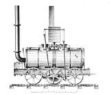
The first full-scale working railway steam locomotive was the 3 ft (914 mm) gauge Coalbrookdale Locomotive, built by Trevithick in 1802. It was constructed for the
Trevithick visited the Newcastle area in 1804 and had a ready audience of colliery (coal mine) owners and engineers. The visit was so successful that the colliery railways in north-east England became the leading centre for experimentation and development of the steam locomotive.[21] Trevithick continued his own steam propulsion experiments through another trio of locomotives, concluding with the Catch Me Who Can in 1808, first in the world to haul fare-paying passengers.

In 1812,
George Stephenson
In 1825, Stephenson built
United States

Before the arrival of British imports, some domestic steam locomotive prototypes were built and tested in the United States, including John Fitch's miniature prototype. A prominent full sized example was Col. John Steven's "steam wagon" which was demonstrated on a loop of track in Hoboken, New Jersey in 1825.[24]
Many of the earliest locomotives for commercial use on American railroads were imported from Great Britain, including first the
As of 2021[update], the original John Bull was on static display in the National Museum of American History in Washington, D.C.[27] The replica is preserved at the Railroad Museum of Pennsylvania.[28]
Continental Europe


In Germany, the first working steam locomotive was a rack-and-pinion engine, similar to the Salamanca, designed by the British locomotive pioneer

In Russia, the first steam locomotive was built in 1834 by Cherepanovs, however, it suffered from the lack of coal in the area and was replaced with horse traction after all the woods nearby had been cut down. The first Russian Tsarskoye Selo steam railway started in 1837 with locomotives purchased from Robert Stephenson and Company.
In 1837, the first steam railway started in Austria on the
In 1838, the third steam locomotive to be built in Germany, the
The first steam locomotives operating in Italy were the Bayard and the Vesuvio, running on the
The first railway line over Swiss territory was the Strasbourg–Basel line opened in 1844. Three years later, in 1847, the first fully Swiss railway line, the Spanisch Brötli Bahn, from Zürich to Baden was opened.
Australia
The arid nature of south Australia posed distinctive challenges to their early steam locomotion network. The high concentration of
Components

| Key to numbered components | |||||||
|---|---|---|---|---|---|---|---|
| No. | Item | No. | Item | No. | Item | No. | Item |
| 1 | Tender | 13 | Smokebox door | 25 | Valve | 37 | Coal bunker |
| 2 | Cab | 14 | Trailing truck / Rear bogie | 26 | Valve chest / Steam chest | 38 | Grate / Fire grate |
| 3 | Safety valves | 15 | Running board / Foot board | 27 | Firebox | 39 | Ashpan hopper |
| 4 | Reach rod | 16 | Frame | 28 | Boiler tubes | 40 | Journal box |
| 5 | Whistle | 17 | Brake shoe | 29 | Boiler | 41 | Equalising beams / Equalising levers / Equalising bars |
| 6 | Generator / Turbo generator | 18 | Sand pipe | 30 | Superheater tubes | 42 | Leaf springs |
| 7 | Sand dome | 19 | Side rods / Coupling rods | 31 | Regulator valve / Throttle valve | 43 | Driving wheel / Driver |
| 8 | Throttle lever / Regulator lever | 20 | Valve gear / Motion | 32 | Superheater | 44 | Pedestal / Saddle |
| 9 | Steam dome | 21 | Connecting rod / Main rod | 33 | Smokestack / Chimney | 45 | Blast pipe |
| 10 | Air pump / Compressor | 22 | Piston rod | 34 | Headlight | 46 | Pilot truck (pony truck if single axle) / Leading bogie |
| 11 | Smokebox | 23 | Piston | 35 | Brake hose | 47 | Pilot / Cowcatcher |
| 12 | Steam pipe | 24 | Cylinder | 36 | Water compartment | 48 | Coupler / Coupling |
| Descriptions of these components are here. | |||||||
Boiler
The

A boiler consists of a firebox where the fuel is burned, a barrel where water is turned into steam, and a smokebox which is kept at a slightly lower pressure than outside the firebox.
Solid fuel, such as wood, coal or coke, is thrown into the firebox through a door by a
The fire-tube boiler has internal tubes connecting the firebox to the smokebox through which the combustion gases flow transferring heat to the water. All the tubes together provide a large contact area, called the tube heating surface, between the gas and water in the boiler. Boiler water surrounds the firebox to stop the metal from becoming too hot. This is another area where the gas transfers heat to the water and is called the firebox heating surface. Ash and char collect in the smokebox as the gas gets drawn up the chimney (stack or smokestack in the US) by the exhaust steam from the cylinders.
The pressure in the boiler has to be monitored using a gauge mounted in the cab. Steam pressure can be released manually by the driver or fireman. If the pressure reaches the boiler's design working limit, a safety valve opens automatically to reduce the pressure[30] and avoid a catastrophic accident.

The exhaust steam from the engine cylinders shoots out of a nozzle pointing up the chimney in the smokebox. The steam entrains or drags the smokebox gases with it which maintains a lower pressure in the smokebox than that under the firebox grate. This pressure difference causes air to flow up through the coal bed and keeps the fire burning.
The search for thermal efficiency greater than that of a typical fire-tube boiler led engineers, such as Nigel Gresley, to consider the water-tube boiler. Although he tested the concept on the LNER Class W1, the difficulties during development exceeded the will to increase efficiency by that route.
The steam generated in the boiler not only moves the locomotive, but is also used to operate other devices such as the whistle, the air compressor for the brakes, the pump for replenishing the water in the boiler and the passenger car heating system. The constant demand for steam requires a periodic replacement of water in the boiler. The water is kept in a tank in the locomotive tender or wrapped around the boiler in the case of a
While the locomotive is producing steam, the amount of water in the boiler is constantly monitored by looking at the water level in a transparent tube, or sight glass. Efficient and safe operation of the boiler requires keeping the level in between lines marked on the sight glass. If the water level is too high, steam production falls, efficiency is lost and water is carried out with the steam into the cylinders, possibly causing mechanical damage. More seriously, if the water level gets too low, the crown sheet (top sheet) of the firebox becomes exposed. Without water on top of the sheet to transfer away the heat of combustion, it softens and fails, letting high-pressure steam into the firebox and the cab. The development of the fusible plug, a temperature-sensitive device, ensured a controlled venting of steam into the firebox to warn the fireman to add water.
Scale builds up in the boiler and prevents adequate heat transfer, and corrosion eventually degrades the boiler materials to the point where it needs to be rebuilt or replaced. Start-up on a large engine may take hours of preliminary heating of the boiler water before sufficient steam is available.
Although the boiler is typically placed horizontally, for locomotives designed to work in locations with steep slopes it may be more appropriate to consider a vertical boiler or one mounted such that the boiler remains horizontal but the wheels are inclined to suit the slope of the rails.
Steam circuit
This section needs additional citations for verification. (April 2021) |

The steam generated in the boiler fills the space above the water in the partially filled boiler. Its maximum working pressure is limited by spring-loaded safety valves. It is then collected either in a perforated tube fitted above the water level or by a dome that often houses the regulator valve, or throttle, the purpose of which is to control the amount of steam leaving the boiler. The steam then either travels directly along and down a steam pipe to the engine unit or may first pass into the wet header of a superheater, the role of the latter being to improve thermal efficiency and eliminate water droplets suspended in the "saturated steam", the state in which it leaves the boiler. On leaving the superheater, the steam exits the dry header of the superheater and passes down a steam pipe, entering the steam chests adjacent to the cylinders of a reciprocating engine. Inside each steam chest is a sliding valve that distributes the steam via ports that connect the steam chest to the ends of the cylinder space. The role of the valves is twofold: admission of each fresh dose of steam, and exhaust of the used steam once it has done its work.
The cylinders are double-acting, with steam admitted to each side of the piston in turn. In a two-cylinder locomotive, one cylinder is located on each side of the vehicle. The cranks are set 90° out of phase. During a full rotation of the driving wheel, steam provides four power strokes; each cylinder receives two injections of steam per revolution. The first stroke is to the front of the piston and the second stroke to the rear of the piston; hence two working strokes. Consequently, two deliveries of steam onto each piston face in the two cylinders generates a full revolution of the driving wheel. Each piston is attached to the driving axle on each side by a connecting rod, and the driving wheels are connected together by
Each
Exhaust steam is directed upwards out of the locomotive through the chimney, by way of a nozzle called a
Running gear


Running gear includes the brake gear,
Locomotives with total adhesion, where all of the wheels are coupled together, generally lack stability at speed. To counter this, locomotives often fit unpowered
Railroads generally preferred locomotives with fewer axles, to reduce maintenance costs. The number of axles required was dictated by the maximum axle loading of the railroad in question. A builder would typically add axles until the maximum weight on any one axle was acceptable to the railroad's maximum axle loading. A locomotive with a wheel arrangement of two lead axles, two drive axles, and one trailing axle was a high-speed machine. Two lead axles were necessary to have good tracking at high speeds. Two drive axles had a lower reciprocating mass than three, four, five or six coupled axles. They were thus able to turn at very high speeds due to the lower reciprocating mass. A trailing axle was able to support a huge firebox, hence most locomotives with the wheel arrangement of 4-4-2 (American Type Atlantic) were called free steamers and were able to maintain steam pressure regardless of throttle setting.
Chassis
The chassis, or locomotive frame, is the principal structure onto which the boiler is mounted and which incorporates the various elements of the running gear. The boiler is rigidly mounted on a "saddle" beneath the smokebox and in front of the boiler barrel, but the firebox at the rear is allowed to slide forward and backwards, to allow for expansion when hot.
European locomotives usually use "plate frames", where two vertical flat plates form the main chassis, with a variety of spacers and a
American practice for many years was to use built-up bar frames, with the smokebox saddle/cylinder structure and drag beam integrated therein. In the 1920s, with the introduction of "superpower", the cast-steel locomotive bed became the norm, incorporating frames, spring hangers, motion brackets, smokebox saddle and cylinder blocks into a single complex, sturdy but heavy casting. A SNCF design study using welded tubular frames gave a rigid frame with a 30% weight reduction.[35]
Fuel and water

Generally, the largest locomotives are permanently coupled to a
The fuel used depended on what was economically available to the railway. In the UK and other parts of Europe, plentiful supplies of coal made this the obvious choice from the earliest days of the steam engine. Until 1870,
During World War 2, a number of Swiss steam
A number of tourist lines and heritage locomotives in Switzerland, Argentina and Australia have used light diesel-type oil.[38]
Water was supplied at stopping places and locomotive depots from a dedicated water tower connected to water cranes or gantries. In the UK, the US and France, water troughs (track pans in the US) were provided on some main lines to allow locomotives to replenish their water supply without stopping, from rainwater or snowmelt that filled the trough due to inclement weather. This was achieved by using a deployable "water scoop" fitted under the tender or the rear water tank in the case of a large tank engine; the fireman remotely lowered the scoop into the trough, the speed of the engine forced the water up into the tank, and the scoop was raised again once it was full.

Water is essential for the operation of a steam locomotive. As Swengel argued:
It has the highest specific heat of any common substance; that is, more thermal energy is stored by heating water to a given temperature than would be stored by heating an equal mass of steel or copper to the same temperature. In addition, the property of vapourising (forming steam) stores additional energy without increasing the temperature… water is a very satisfactory medium for converting thermal energy of fuel into mechanical energy.[39]
Swengel went on to note that "at low temperature and relatively low boiler outputs", good water and regular boiler washout was an acceptable practice, even though such maintenance was high. As steam pressures increased, however, a problem of "foaming" or "priming" developed in the boiler, wherein dissolved solids in the water formed "tough-skinned bubbles" inside the boiler, which in turn were carried into the steam pipes and could blow off the cylinder heads. To overcome the problem, hot mineral-concentrated water was deliberately wasted (blown down) from the boiler periodically. Higher steam pressures required more blowing-down of water out of the boiler. Oxygen generated by boiling water attacks the boiler, and with increased steam pressure the rate of rust (iron oxide) generated inside the boiler increases. One way to help overcome the problem was water treatment. Swengel suggested that these problems contributed to the interest in electrification of railways.[39]
In the 1970s, L.D. Porta developed a sophisticated system of heavy-duty chemical water treatment (Porta Treatment) that not only keeps the inside of the boiler clean and prevents corrosion, but modifies the foam in such a way as to form a compact "blanket" on the water surface that filters the steam as it is produced, keeping it pure and preventing carry-over into the cylinders of water and suspended abrasive matter.[40][41]
Some steam locomotives have been run on alternative fuels such as used cooking oil like Grand Canyon Railway 4960, Grand Canyon Railway 29, U.S. Sugar 148, and the Disneyland Railroad Locomotives.[42][43][44][45][46][47][48]
Crew

A steam locomotive is normally controlled from the boiler's
Fittings and appliances
All locomotives are fitted with a variety of appliances. Some of these relate directly to the operation of the steam engine; others are for signalling, train control or other purposes. In the United States, the Federal Railroad Administration mandated the use of certain appliances over the years in response to safety concerns. The most typical appliances are as follows:
Steam pumps and injectors
Water (
Vertical glass tubes, known as water gauges or water glasses, show the level of water in the boiler and are carefully monitored at all times while the boiler is being fired. Before the 1870s it was more common to have a series of try-cocks fitted to the boiler within reach of the crew; each try cock (at least two and usually three were fitted) was mounted at a different level. By opening each try-cock and seeing if steam or water vented through it, the level of water in the boiler could be estimated with limited accuracy. As boiler pressures increased the use of try-cocks became increasingly dangerous and the valves were prone to blockage with scale or sediment, giving false readings. This led to their replacement with the sight glass. As with the injectors, two glasses with separate fittings were usually installed to provide independent readings.
Boiler insulation
The term for pipe and boiler insulation is "lagging"[49] which derives from the cooper's term for a wooden barrel stave.[50] Two of the earliest steam locomotives used wooden lagging to insulate their boilers: the Salamanca, the first commercially successful steam locomotive, built in 1812,[4] and the Locomotion No. 1, the first steam locomotive to carry passengers on a public rail line. Large amounts of heat are wasted if a boiler is not insulated. Early locomotives used lags, shaped wooden staves, fitted lengthways along the boiler barrel, and held in place by hoops, metal bands, the terms and methods are from cooperage.
-
 The Salamanca (1812)
 -
 Locomotion No. 1, (1825)
 -
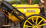 Rocket (1829; a replica)
.jpg)

_close_up_of_the_boiler_lagging.jpg)
Improved insulating methods included applying a thick paste containing a porous mineral such as
The lagging is protected by a close-fitted sheet-metal casing[52] known as boiler clothing or cleading.
Effective lagging is particularly important for fireless locomotives; however, in recent times under the influence of L.D. Porta, "exaggerated" insulation has been practised for all types of locomotive on all surfaces liable to dissipate heat, such as cylinder ends and facings between the cylinders and the mainframes. This considerably reduces engine warmup time with a marked increase in overall efficiency.
Safety valves
Early locomotives were fitted with a valve controlled by a weight suspended from the end of a lever, with the steam outlet being stopped by a cone-shaped valve. As there was nothing to prevent the weighted lever from bouncing when the locomotive ran over irregularities in the track, thus wasting steam, the weight was later replaced by a more stable spring-loaded column, often supplied by Salter, a well-known spring scale manufacturer. The danger of these devices was that the driving crew could be tempted to add weight to the arm to increase pressure. Most early boilers were fitted with a tamper-proof "lockup" direct-loaded ball valve protected by a cowl. In the late 1850s, John Ramsbottom introduced a safety valve that became popular in Britain during the latter part of the 19th century. Not only was this valve tamper-proof, but tampering by the driver could only have the effect of easing pressure. George Richardson's safety valve was an American invention introduced in 1875,[53] and was designed to release the steam only at the moment when the pressure attained the maximum permitted. This type of valve is in almost universal use at present. Britain's Great Western Railway was a notable exception to this rule, retaining the direct-loaded type until the end of its separate existence, because it was considered that such a valve lost less pressure between opening and closing.
Pressure gauge
The earliest locomotives did not show the pressure of steam in the boiler, but it was possible to estimate this by the position of the safety valve arm which often extended onto the firebox back plate; gradations marked on the spring column gave a rough indication of the actual pressure. The promoters of the
Spark arrestors and smokeboxes
- Spark arrestor and self-cleaning smokebox

Wood-burners emit large quantities of flying sparks which necessitate an efficient spark-arresting device generally housed in the smokestack. Many different types were fitted,[55] the most common early type being the Bonnet stack that incorporated a cone-shaped deflector placed before the mouth of the chimney pipe, and a wire screen covering the wide stack exit. A more efficient design was the Radley and Hunter centrifugal stack patented in 1850 (commonly known as the diamond stack), incorporating baffles so oriented as to induce a swirl effect in the chamber that encouraged the embers to burn out and fall to the bottom as ash. In the self-cleaning smokebox the opposite effect was achieved: by allowing the flue gasses to strike a series of deflector plates, angled in such a way that the blast was not impaired, the larger particles were broken into small pieces that would be ejected with the blast, rather than settle in the bottom of the smokebox to be removed by hand at the end of the run. As with the arrestor, a screen was incorporated to retain any large embers.[56]
Locomotives of the British Railways standard classes fitted with self-cleaning smokeboxes were identified by a small cast oval plate marked "S.C.", fitted at the bottom of the smokebox door. These engines required different disposal procedures and the plate highlighted this need to depot staff.
Stokers
A factor that limits locomotive performance is the rate at which fuel is fed into the fire. In the early 20th century some locomotives became so large that the fireman could not shovel coal fast enough.[52] In the United States, various steam-powered mechanical stokers became standard equipment and were adopted and used elsewhere including Australia and South Africa.
Feedwater heating
Introducing cold water into a boiler reduces power, and from the 1920s a variety of heaters were incorporated. The most common type for locomotives was the exhaust steam feedwater heater that piped some of the exhaust through small tanks mounted on top of the boiler or smokebox or into the tender tank; the warm water then had to be delivered to the boiler by a small auxiliary steam pump. The rare economiser type differed in that it extracted residual heat from the exhaust gases. An example of this is the pre-heater drum(s) found on the Franco-Crosti boiler.
The use of live steam and exhaust steam injectors also assists in the pre-heating of boiler feedwater to a small degree, though there is no efficiency advantage to live steam injectors. Such pre-heating also reduces the
Condensers and water re-supply


Steam locomotives consume vast quantities of water because they operate on an open cycle, expelling their steam immediately after a single use rather than recycling it in a closed loop as stationary and marine steam engines do. Water was a constant logistical problem, and condensing engines were devised for use in desert areas. These engines had huge radiators in their tenders and instead of exhausting steam out of the funnel it was captured, passed back to the tender and condensed. The cylinder lubricating oil was removed from the exhausted steam to avoid a phenomenon known as priming, a condition caused by foaming in the boiler which would allow water to be carried into the cylinders causing damage because of its incompressibility. The most notable engines employing condensers (Class 25, the "puffers which never puff"[57]) worked across the Karoo desert of South Africa from the 1950s until the 1980s.
Some British and American locomotives were equipped with scoops which collected water from "water troughs" (
Steam locomotives working on underground railways (such as London's Metropolitan Railway) were fitted with condensing apparatus to prevent steam from escaping into the railway tunnels. These were still being used between King's Cross and Moorgate into the early 1960s.
Braking
Steam locomotives usually have their own braking system, independent from the rest of the train. Locomotive brakes employ large shoes which press against the driving wheel treads. They can be either air brakes or steam brakes. In addition, they nearly always have a handbrake to keep the locomotive stationary when there is no steam pressure to power the other braking systems.
Because of the limited braking force provided by locomotive-only brakes, many steam locomotives were fitted with a train brake. These came in two main varieties;
Air brakes, invented by George Westinghouse, use a steam-driven air compressor mounted on the side of the boiler to create the compressed air needed to power the brake system.[59] Air brakes were the predominant form of train braking in most countries during the steam era.
The primary competitor to the air brake was the
Steam locomotives are fitted with
Lubrication

The pistons and valves on the earliest locomotives were
As speeds and distances increased, mechanisms were developed that injected thick mineral oil into the steam supply. The first, a displacement lubricator, mounted in the cab, uses a controlled stream of steam condensing into a sealed container of oil. Water from the condensed steam displaces the oil into pipes. The apparatus is usually fitted with sight-glasses to confirm the rate of supply. A later method uses a mechanical pump worked from one of the crossheads. In both cases, the supply of oil is proportional to the speed of the locomotive.
Lubricating the frame components (axle bearings,
Crankpin and crosshead bearings carry small cup-shaped reservoirs for oil. These have feed pipes to the bearing surface that start above the normal fill level, or are kept closed by a loose-fitting pin, so that only when the locomotive is in motion does oil enter. In United Kingdom practice, the cups are closed with simple corks, but these have a piece of porous cane pushed through them to admit air. It is customary for a small capsule of pungent oil (aniseed or garlic) to be incorporated in the bearing metal to warn if the lubrication fails and excess heating or wear occurs.[64]
Blower
When the locomotive is running under power, a draught on the fire is created by the exhaust steam directed up the chimney by the blastpipe. Without draught, the fire will quickly die down and steam pressure will fall. When the locomotive is stopped, or coasting with the regulator closed, there is no exhaust steam to create a draught, so the draught is maintained by means of a blower. This is a ring placed either around the base of the chimney, or around the blast pipe orifice, containing several small steam nozzles directed up the chimney. These nozzles are fed with steam directly from the boiler, controlled by the blower valve. When the regulator is open, the blower valve is closed; when the driver intends to close the regulator, he will first open the blower valve. It is important that the blower be opened before the regulator is closed, since without draught on the fire, there may be backdraught – where atmospheric air blows down the chimney, causing the flow of hot gases through the boiler tubes to be reversed, with the fire itself being blown through the firehole onto the footplate, with serious consequences for the crew. The risk of backdraught is higher when the locomotive enters a tunnel because of the pressure shock. The blower is also used to create draught when steam is being raised at the start of the locomotive's duty, at any time when the driver needs to increase the draught on the fire, and to clear smoke from the driver's line of vision.[65]
Blowbacks were fairly common. In a 1955 report on an accident near Dunstable, the Inspector wrote, "In 1953 twenty-three cases, which were not caused by an engine defect, were reported and they resulted in 26 enginemen receiving injuries. In 1954, the number of occurrences and of injuries were the same and there was also one fatal casualty."[66] They remain a problem, as evidenced by the 2012 incident with BR Standard Class 7 70013 Oliver Cromwell.
Buffers
In British and European (except former Soviet Union countries) practice, locomotives usually have buffers at each end to absorb compressive loads ("buffets"[67]). The tensional load of drawing the train (draft force) is carried by the coupling system. Together these control slack between the locomotive and train, absorb minor impacts and provide a bearing point for pushing movements.
In Canadian and American practice, all of the forces between the locomotive and cars are handled through the coupler – particularly the
Pilots
A
Headlights

When night operations began, railway companies in some countries equipped their locomotives with lights to allow the driver to see what lay ahead of the train, or to enable others to see the locomotive. Headlights were originally oil or acetylene lamps, but when electric arc lamps became available in the late 1880s, they quickly replaced the older types.
Britain did not adopt bright headlights as they would affect night vision and so could mask the low-intensity oil lamps used in the
In some countries, heritage steam operation continues on the national network. Some railway authorities have mandated powerful headlights on at all times, including during daylight. This was to further inform the public or track workers of any active trains.
Bells and whistles
Locomotives used bells and steam whistles from earliest days of steam locomotion. In the United States, India and Canada, bells warned of a train in motion. In Britain, where all lines are by law fenced throughout,[69] bells were only a requirement on railways running on a road (i.e. not fenced off), for example a tramway along the side of the road or in a dockyard. Consequently, only a minority of locomotives in the UK carried bells. Whistles are used to signal personnel and give warnings. Depending on the terrain the locomotive was being used in, the whistle could be designed for long-distance warning of impending arrival, or for more localised use.
Early bells and whistles were sounded through pull-string cords and levers. Automatic bell ringers came into widespread use in the US after 1910.[70]
Automatic control
From the early 20th century operating companies in such countries as Germany and Britain began to fit locomotives with Automatic Warning System (AWS) in-cab signalling, which automatically applied the brakes when a signal was passed at "caution". In Britain, these became mandatory in 1956. In the United States, the Pennsylvania Railroad also fitted their locomotives with such devices.[citation needed]
Booster engines
The booster engine was an auxiliary steam engine which provided extra tractive effort for starting. It was a low-speed device, usually mounted on the trailing truck. It was disengaged via an idler gear at a low speed, e.g. 30 km/h. Boosters were widely used in the US and tried experimentally in Britain and France. On the narrow-gauged New Zealand railway system, six Kb 4-8-4 locomotives were fitted with boosters, the only 3 ft 6 in (1,067 mm) gauge engines in the world to have such equipment.
Booster engines were also fitted to tender trucks in the US and known as auxiliary locomotives. Two and even three truck axles were connected together using side rods which limited them to slow-speed service.[71]
Firedoor
The firedoor is used to cover the firehole when coal is not being added. It serves two purposes, first, it prevents air being drawn over the top of the fire, rather forcing it to be drawn through it. The second purpose is to safeguard the train crew against blowbacks. It does, however, have a means to allow some air to pass over the top of the fire (referred to as "secondary air") to complete the combustion of gases produced by the fire.
Firedoors come in multiple designs, the most basic of which is a single piece which is hinged on one side and can swing open onto the footplate. This design has two issues. First, it takes up much room on the footplate, and second, the draught will tend to pull it completely shut, thus cutting off any secondary air. To compensate for this some locomotives are fitted with a latch that prevents the firedoor from closing completely whereas others have a small vent on the door that may be opened to allow secondary air to flow through. Though it was considered to design a firedoor that opens inwards into the firebox thus preventing the inconvenience caused on the footplate, such a door would be exposed to the full heat of the fire and would likely deform, thus becoming useless.
A more popular type of firedoor consists of a two-piece sliding door operated by a single lever. There are tracks above and below the firedoor which the door runs along. These tracks are prone to becoming jammed by debris and the doors required more effort to open than the aforementioned swinging door. In order to address this some firedoors use powered operation which utilized a steam or air cylinder to open the door. Among these are the butterfly doors which pivot at the upper corner, the pivoting action offers low resistance to the cylinder that opens the door.[72]
Variations
Numerous variations on the basic locomotive occurred as railways attempted to improve efficiency and performance.
Cylinders
Early steam locomotives had two cylinders, one either side, and this practice persisted as the simplest arrangement. The cylinders could be mounted between the mainframes (known as "inside" cylinders), or mounted outside the frames and driving wheels ("outside" cylinders). Inside cylinders drive cranks built into the driving axle; outside cylinders drive cranks on extensions to the driving axles.
Later designs employed three or four cylinders, mounted both inside and outside the frames, for a more even power cycle and greater power output.
Most British express-passenger locomotives built between 1930 and 1950 were
Valve gear
Early locomotives used a simple valve gear that gave full power in either forward or reverse.[54] Soon the Stephenson valve gear allowed the driver to control cut-off; this was largely superseded by Walschaerts valve gear and similar patterns. Early locomotive designs using slide valves and outside admission were relatively easy to construct, but inefficient and prone to wear.[54] Eventually, slide valves were superseded by inside admission piston valves, though there were attempts to apply poppet valves (commonly used in stationary engines) in the 20th century. Stephenson valve gear was generally placed within the frame and was difficult to access for maintenance; later patterns applied outside the frame were more readily visible and maintained.
Compounding
Compound locomotives were used from 1876, expanding the steam twice or more through separate cylinders – reducing thermal losses caused by cylinder cooling. Compound locomotives were especially useful in trains where long periods of continuous efforts were needed. Compounding contributed to the dramatic increase in power achieved by André Chapelon's rebuilds from 1929. A common application was in articulated locomotives, the most common being that designed by Anatole Mallet, in which the high-pressure stage was attached directly to the boiler frame; in front of this was pivoted a low-pressure engine on its own frame, which takes the exhaust from the rear engine.[74]
Articulated locomotives
Very powerful locomotives tend to be longer than those with lower power output, but long rigid-framed designs are impracticable for the tight curves frequently found on narrow-gauge railways. Various designs for articulated locomotives were developed to overcome this problem. The Mallet and the Garratt were the two most popular. They had a single boiler and two engine units (sets of cylinders and driving wheels): both of the Garratt's engine units were on swivelling frames, whereas one of the Mallet's was on a swivelling frame and the other was fixed under the boiler unit. A few triplex locomotives were also designed, with a third engine unit under the tender. Other less common variations included the Fairlie locomotive, which had two boilers back-to-back on a common frame, with two separate engine units.
Duplex types
Duplex locomotives, containing two engines in one rigid frame, were also tried, but were not notably successful. For example, the 4-4-4-4 Pennsylvania Railroad class T1, designed for very fast running, suffered recurring and ultimately unfixable slippage problems throughout their careers.[75]
Geared locomotives
For locomotives where a high starting torque and low speed were required, the conventional direct drive approach was inadequate. "Geared" steam locomotives, such as the Shay, the Climax and the Heisler, were developed to meet this need on industrial, logging, mine and quarry railways. The common feature of these three types was the provision of reduction gearing and a drive shaft between the crankshaft and the driving axles. This arrangement allowed the engine to run at a much higher speed than the driving wheels compared to the conventional design, where the ratio is 1:1.
Cab forward
In the United States on the
The only preserved cab forward locomotive is Southern Pacific 4294 in Sacramento, California.
In France, the three Heilmann locomotives were built with a cab forward design.
Steam turbines

Steam turbines were created as an attempt to improve the operation and efficiency of steam locomotives. Experiments with
Fireless locomotive

In a fireless locomotive the boiler is replaced by a
Another class of fireless locomotive is a compressed-air locomotive.[citation needed]
Mixed power
Steam diesel hybrid locomotive
Mixed power locomotives, utilising both steam and diesel propulsion, have been produced in Russia, Britain and Italy.
Electric-steam locomotive
Under unusual conditions (lack of coal, abundant hydroelectricity) some locomotives in Switzerland were modified to use electricity to heat the boiler, making them electric-steam locomotives.[76]
Steam-electric locomotive
A steam-electric locomotive uses electric transmission, like
Categorisation

Steam locomotives are categorised by their wheel arrangement. The two dominant systems for this are the
The Whyte notation, used in most English-speaking and Commonwealth countries, represents each set of wheels with a number. These numbers typically represented the number of unpowered leading wheels, followed by the number of driving wheels (sometimes in several groups), followed by the number of un-powered trailing wheels. For example, a yard engine with only 4 driven wheels would be categorised as a 0-4-0 wheel arrangement. A locomotive with a 4-wheel leading truck, followed by 6 drive wheels, and a 2-wheel trailing truck, would be classed as a 4-6-2. Different arrangements were given names which usually reflect the first usage of the arrangement; for instance, the "Santa Fe" type (2-10-2) is so called because the first examples were built for the Atchison, Topeka and Santa Fe Railway. These names were informally given and varied according to region and even politics.
The UIC classification is used mostly in European countries apart from the United Kingdom. It designates consecutive pairs of wheels (informally "axles") with a number for non-driving wheels and a capital letter for driving wheels (A=1, B=2, etc.) So a Whyte 4-6-2 designation would be an equivalent to a 2-C-1 UIC designation.
On many railroads, locomotives were organised into classes. These broadly represented locomotives which could be substituted for each other in service, but most commonly a class represented a single design. As a rule classes were assigned some sort of code, generally based on the wheel arrangement. Classes also commonly acquired nicknames, such as Pug (a small shunting locomotive), representing notable (and sometimes uncomplimentary) features of the locomotives.[77][78]
Performance
Measurement
In the steam locomotive era, two measures of locomotive performance were generally applied. At first, locomotives were rated by tractive effort, defined as the average force developed during one revolution of the driving wheels at the railhead.[39] This can be roughly calculated by multiplying the total piston area by 85% of the boiler pressure (a rule of thumb reflecting the slightly lower pressure in the steam chest above the cylinder) and dividing by the ratio of the driver diameter over the piston stroke. However, the precise formula is

where d is the bore of the cylinder (diameter) in inches, s is the cylinder stroke, in inches, P is boiler pressure in pounds per square inch, D is the diameter of the driving wheel in inches, and c is a factor that depends on the effective cut-off.[79] In the US, c is usually set at 0.85, but lower on engines that have maximum cutoff limited to 50–75%.
The tractive effort is only the "average" force, as not all effort is constant during the one revolution of the drivers. At some points of the cycle, only one piston is exerting turning moment and at other points, both pistons are working. Not all boilers deliver full power at starting, and the tractive effort also decreases as the rotating speed increases.[39]
Tractive effort is a measure of the heaviest load a locomotive can start or haul at very low speed over the
British railway companies have been reluctant to disclose figures for drawbar horsepower and have usually relied on
Relation to wheel arrangement
Classification is indirectly connected to locomotive performance. Given adequate proportions of the rest of the locomotive, power output is determined by the size of the fire, and for a bituminous coal-fuelled locomotive, this is determined by the grate area. Modern non-compound locomotives are typically able to produce about 40 drawbar horsepower per square foot of grate. Tractive force, as noted earlier, is largely determined by the boiler pressure, the cylinder proportions and the size of the driving wheels. However, it is also limited by the weight on the driving wheels (termed "adhesive weight"), which needs to be at least four times the tractive effort.[52]
The weight of the locomotive is roughly proportional to the power output; the number of axles required is determined by this weight divided by the axleload limit for the trackage where the locomotive is to be used. The number of driving wheels is derived from the adhesive weight in the same manner, leaving the remaining axles to be accounted for by the leading and trailing bogies.
As a rule,
As locomotive types began to diverge in the late 19th century, freight engine designs at first emphasised tractive effort, whereas those for passenger engines emphasised speed. Over time, freight locomotive size increased, and the overall number of axles increased accordingly; the leading bogie was usually a single axle, but a trailing truck was added to larger locomotives to support a larger firebox that could no longer fit between or above the driving wheels. Passenger locomotives had leading bogies with two axles, fewer driving axles, and very large driving wheels in order to limit the speed at which the reciprocating parts had to move.
In the 1920s, the focus in the United States turned to horsepower, epitomised by the "super power" concept promoted by the Lima Locomotive Works, although tractive effort was still the prime consideration after World War I to the end of steam. Goods trains were designed to run faster, while passenger locomotives needed to pull heavier loads at speed. This was achieved by increasing the size of grate and firebox without changes to the rest of the locomotive, requiring the addition of a second axle to the trailing truck. Freight 2-8-2s became 2-8-4s while 2-10-2s became 2-10-4s. Similarly, passenger 4-6-2s became 4-6-4s. In the United States this led to a convergence on the dual-purpose 4-8-4 and the 4-6-6-4 articulated configuration, which was used for both freight and passenger service.[80] Mallet locomotives went through a similar transformation, evolving from bank engines into huge mainline locomotives with much larger fireboxes; their driving wheels were also increased in size in order to allow faster running.
Manufacture
Most-manufactured classes
The most-manufactured single class of steam locomotive in the world is the
In Britain, 863 of the GWR 5700 Class were built, and 943 of the DX class of the London and North Western Railway – including 86 engines built for the Lancashire and Yorkshire Railway.[81]
United Kingdom

.jpg)
Before the
Between 1923 and 1947, the Big Four railway companies (the Great Western Railway, the London, Midland & Scottish Railway, the
From 1948, British Railways (BR) allowed the former Big Four companies (now designated as "Regions") to continue to produce their own designs, but also created a range of standard locomotives which supposedly combined the best features from each region. Although a policy of dieselisation was adopted in 1955, BR continued to build new steam locomotives until 1960, with the final engine being named Evening Star.[83]
Some independent manufacturers produced steam locomotives for a few more years, with the last British-built industrial steam locomotive being constructed by Hunslet in 1971. Since then, a few specialised manufacturers have continued to produce small locomotives for narrow gauge and miniature railways, but as the prime market for these is the tourist and heritage railway sector, the demand for such locomotives is limited. In November 2008, a new build main line steam locomotive, 60163 Tornado, was tested on UK mainlines for eventual charter and tour use.
Sweden
In the 19th and early 20th centuries, most Swedish steam locomotives were manufactured in Britain. Later, however, most steam locomotives were built by local factories including NOHAB in Trollhättan and ASJ in Falun. One of the most successful types was the class "B" (4-6-0), inspired by the Prussian class P8. Many of the Swedish steam locomotives were preserved during the Cold War in case of war. During the 1990s, these steam locomotives were sold to non-profit associations or abroad, which is why the Swedish class B, class S (2-6-4) and class E2 (2-8-0) locomotives can now be seen in Britain, the Netherlands, Germany and Canada.
United States

Locomotives for American railroads were nearly always built in the United States with very few imports, except in the earliest days of steam engines. This was due to the basic differences of markets in the United States which initially had many small markets located large distances apart, in contrast to Europe's higher density of markets. Locomotives that were cheap and rugged and could go large distances over cheaply built and maintained tracks were required. Once the manufacture of engines was established on a wide scale there was very little advantage to buying an engine from overseas that would have to be customised to fit the local requirements and track conditions. Improvements in engine design of both European and US origin were incorporated by manufacturers when they could be justified in a generally very conservative and slow-changing market. With the notable exception of the USRA standard locomotives built during World War I, in the United States, steam locomotive manufacture was always semi-customised. Railroads ordered locomotives tailored to their specific requirements, though some basic design features were always present. Railroads developed some specific characteristics; for example, the Pennsylvania Railroad and the Great Northern Railway had a preference for the Belpaire firebox.[84] In the United States, large-scale manufacturers constructed locomotives for nearly all rail companies, although nearly all major railroads had shops capable of heavy repairs and some railroads (for example, the Norfolk and Western Railway and the Pennsylvania Railroad, which had two erecting shops) constructed locomotives entirely in their own shops.[85][86] Companies manufacturing locomotives in the US included Baldwin Locomotive Works, American Locomotive Company (ALCO), and Lima Locomotive Works. Altogether, between 1830 and 1950, over 160,000 steam locomotives were built in the United States, with Baldwin accounting for the largest share, nearly 70,000.[87]
Steam locomotives required regular and, compared to a diesel-electric engine, frequent service and overhaul (often at government-regulated intervals in Europe and the US). Alterations and upgrades regularly occurred during overhauls. New appliances were added, unsatisfactory features removed, cylinders improved or replaced. Almost any part of the locomotive, including boilers, was replaced or upgraded. When service or upgrades got too expensive the locomotive was traded off or retired.[citation needed] On the Baltimore and Ohio Railroad two 2-10-2 locomotives were dismantled; the boilers were placed onto two new Class T 4-8-2 locomotives and the residual wheel machinery made into a pair of Class U 0-10-0 switchers with new boilers. Union Pacific's fleet of 3-cylinder 4-10-2 engines were converted into two-cylinder engines in 1942, because of high maintenance problems.
Australia

In
The end of steam in general use
The introduction of electric locomotives around the turn of the 20th century and later diesel-electric locomotives spelled the beginning of a decline in the use of steam locomotives, although it was some time before they were phased out of general use.[90] As diesel power (especially with electric transmission) became more reliable in the 1930s, it gained a foothold in North America.[91] The full transition away from steam power in North America took place during the 1950s. In continental Europe, large-scale electrification had replaced steam power by the 1970s. Steam was a familiar technology, adapted well to local facilities, and also consumed a wide variety of fuels; this led to its continued use in many countries until the end of the 20th century.
Steam engines have considerably less thermal efficiency than modern diesels, requiring constant maintenance and labour to keep them operational.[92] Water is required at many points throughout a rail network, making it a major problem in desert areas, as are found in some regions of the United States, Australia and South Africa. In places where water is available, it may be hard, which can cause "scale" to form, composed mainly of calcium carbonate, magnesium hydroxide and calcium sulfate. Calcium and magnesium carbonates tend to be deposited as off-white solids on the inside the surfaces of pipes and heat exchangers. This precipitation is principally caused by thermal decomposition of bicarbonate ions but also happens in cases where the carbonate ion is at saturation concentration.[93] The resulting build-up of scale restricts the flow of water in pipes. In boilers, the deposits impair the flow of heat into the water, reducing the heating efficiency and allowing the metal boiler components to overheat.
The reciprocating mechanism on the driving wheels of a two-cylinder single expansion steam locomotive tended to pound the rails (see hammer blow), thus requiring more maintenance. Raising steam from coal took a matter of hours, and created serious pollution problems. Coal-burning locomotives required fire cleaning and ash removal between turns of duty.[94] Diesel or electric locomotives, by comparison, drew benefit from new custom-built servicing facilities. The smoke from steam locomotives was also deemed objectionable; the first electric and diesel locomotives were developed in response to smoke abatement requirements,[95] although this did not take into account the high level of less-visible pollution in diesel exhaust smoke, especially when idling. In some countries, however, power for electric locomotives is derived from steam generated in power stations, which are often run by coal.
Revival


_35.JPG)
Dramatic increases in the cost of diesel fuel prompted several initiatives to revive steam power.[96][97] However none of these has progressed to the point of production and, as of the early 21st century, steam locomotives operate only in a few isolated regions of the world and in tourist operations.
As early as 1975, railway enthusiasts in the United Kingdom began building new steam locomotives. That year, Trevor Barber completed his 2 ft (610 mm) gauge locomotive Trixie which ran on the Meirion Mill Railway.[98] From the 1990s onwards, the number of new builds being completed rose dramatically with new locos completed by the narrow-gauge Ffestiniog and Corris railways in Wales. The Hunslet Engine Company was revived in 2005, and began building steam locomotives on a commercial basis.[99] A standard-gauge LNER Peppercorn Pacific "Tornado" was completed at Hopetown Works, Darlington, and made its first run on 1 August 2008.[100][101] It entered main line service later in 2008.[102] As of 2009[update] over half-a-dozen projects to build working replicas of extinct steam engines are going ahead, in many cases using existing parts from other types to build them. Examples include BR 72010 Hengist,[103] BR Class 3MT No. 82045, BR Class 2MT No. 84030,[104] Brighton Atlantic Beachy Head,[105] the LMS 5551 The Unknown Warrior project, GWR "47xx 4709, 2999 Lady of Legend, 1014 County of Glamorgan and 6880 Betton Grange projects. These United Kingdom based new build projects are further complemented by the new build Pennsylvania Railroad 5550[106] project in the United States. One of the group's goals is to surpass the steam locomotive speed record held by the 4468 Mallard when the 5550 is completed and for the 5550 to fill in a huge gap in steam locomotive preservation.
In 1980, American financier Ross Rowland established American Coal Enterprises to develop a modernised coal-fired steam locomotive. His ACE 3000 concept attracted considerable attention, but was never built.[107][108]
In 1998, in his book The Red Devil and Other Tales from the Age of Steam,[109] David Wardale put forward the concept of a high-speed high-efficiency "Super Class 5 4-6-0" locomotive for future steam haulage of tour trains on British main lines. The idea was formalised in 2001 by the formation of 5AT Project dedicated to developing and building the 5AT Advanced Technology Steam Locomotive, but it never received any major railway backing.
Locations where new builds are taking place include:[citation needed]
- GWR 1014 County of Glamorgan & GWR 2999 Lady of Legend, both being built at Didcot Railway Centre
- GWR 6880 Betton Grange, GWR 4709 & LMS 5551 The Unknown Warrior, all being built at Llangollen Railway
- LNER 2007 Prince of Wales, Darlington Locomotive Works
- LNER 2001 Cock O' The North, Doncaster
- Pennsylvania Railroad 5550, Pottstown, Pennsylvania[106]
- BR 72010 Hengist, Great Central Railway
- BR 77021, TBA
- BR 82045, Severn Valley Railway
- BR 84030 & LBSCR 32424 Beachy Head, both being built at Bluebell Railway
- MS&LR/GCR 567, Ruddington Great Central Railway, Northern Section
- VR V499, Victoria, Australia
In 2012, the
In Germany, a small number of fireless steam locomotives are still working in industrial service, e.g. at power stations, where an on-site supply of steam is readily available.
The small town of Wolsztyn, Poland, approximately 60 kilometres (37 mi) from the historic city of Poznan, is the last place in the world where one can ride a regularly scheduled passenger train pulled by steam power. The locomotive shed at Wolsztyn is the last of its kind in the world. There are several working locomotives that haul daily commuter service between Wolsztyn, Poznan, Leszo and other neighboring cities. One can partake in footplate courses via The Wolsztyn Experience. There is no place left in the world that still operates daily, non-tourist steam powered commuter/passenger service other than here at Wolsztyn. There are several Polish-built OL49-class 2-6-2 general purpose locomotives and one PT47 class 2-8-2 in regular service. Each May, Wolsztyn is the site of a steam locomotive festival which brings visiting locomotives - often well over a dozen each year all operating. These operations are not done for tourism or museum/historical purposes; this is the last non-diesel rail line on the PKP (Polish State Network) that has been converted to diesel power.
The Swiss company Dampflokomotiv- und Maschinenfabrik
The same company also rebuilt a German DR Class 52.80 2-10-0 locomotive to new standards with modifications such as roller bearings, light oil firing and boiler insulation.[111]
Climate change
The examples and perspective in this section may not represent a worldwide view of the subject. (February 2022) |
The future use of steam locomotives in the United Kingdom is in doubt because of government policy on climate change. The Heritage Railway Association is working with the All-Party Parliamentary Group on Heritage Rail in an effort to continue running steam locomotives on coal.[112]
Many tourist railroads use oil-fired steam locomotives (or have converted their locomotives to run on oil) to reduce their environmental footprint, and because fuel oil can be easier to obtain than coal of the proper type and sizing for locomotives. For example, the Grand Canyon Railway runs its steam locomotives on used vegetable oil.
An organization called the Coalition for Sustainable Rail (CSR) is developing an environmentally friendly coal substitute made from
Steam locomotives in popular culture
Steam locomotives have been present in popular culture since the 19th century. Folk songs from that period including "I've Been Working on the Railroad" and the "Ballad of John Henry" are a mainstay of American music and culture.
Many steam locomotive toys have been made, and railway modelling is a popular hobby.
Steam locomotives are often portrayed in fictional works, notably
The Hogwarts Express also appears in the Harry Potter series of films, portrayed by GWR 4900 Class 5972 Olton Hall in a special Hogwarts livery. The Polar Express appears in the animated movie of the same name.
An elaborate, themed
The Polar Express is recreated on many heritage railroads in the United States, including the North Pole Express pulled by the Pere Marquette 1225 locomotive, which is operated by the Steam Railroading Institute in Owosso, Michigan. According to author Van Allsburg, this locomotive was the inspiration for the story and it was used in the production of the movie.
A number of computer and video games feature steam locomotives.
There are two notable examples of steam locomotives used as charges on heraldic coats of arms. One is that of Darlington, which displays Locomotion No. 1. The other is the original coat of arms of Swindon, not currently in use, which displays a basic steam locomotive.[115][116]
Steam locomotives are a popular topic for coin collectors.[citation needed] The 1950 Silver 5 Peso coin of Mexico has a steam locomotive on its reverse as the prominent feature.
The 20 euro
The novel "Night on the Galactic Railroad"[117] by Kenji Miyazawa is centered on the idea of a steam train traveling among the stars. Miyazawa's novel later inspired Leiji Matsumoto's successful "Galaxy Express 999" series.
Another Japanese televisual franchise, Super Sentai, features monsters based on steam locomotives.
Charge Man, a Robot Master from the fifth installment of the Mega Man series is based on a steam locomotive.
See also
General
Types of steam locomotives
Notes
- ^ Comparable figures for the last-built British Railways freight locomotive, the Class 9F, were 139 long tons (141 t; 156 short tons) and 39,667 lbf (176,450 N).
References
- ISBN 978-0-912318-20-2.
- ^ "Railways". British History Online.
- ISBN 1-85410-878-6.
- ^ a b Hamilton Ellis (1968). The Pictorial Encyclopedia of Railways. Hamlyn Publishing Group. p. 20.
- ^ Ellis, Hamilton (1968). The Pictorial Encyclopedia of Railways. pp. 24–30. Hamlyn Publishing Group.
- ^ "Magnificent Mallard: World's fastest steam locomotive". BBC News. 17 February 2018
- ^ Kratville, William (1972). Big Boy. Kratville Publications.
- doi:10.1093/ref:odnb/2637. (Subscription or UK public library membershiprequired.)
- ^ Payton, Philip (2004). Oxford Dictionary of National Biography. Oxford University Press.
- ^ "Engineering and railway works". British History Online.
- Frederick Warne & Co. pp. 7–9.
- ^ The Railway Magazine, Volume 150, IPC Business Press, 2004, p. 11. Google Books.
- ISBN 978-3-642-36051-0– via Google Books.
- ^ National Park Service. "American Steam Locomotives". Retrieved 14 September 2021.
- ^ "The Legacy of John Fitch". www.craven-hall.org. Archived from the original on 31 October 2020. Retrieved 24 February 2016.
- ISBN 978-1-60844-475-5– via Google Books.
- ^ Francis Trevithick (1872). Life of Richard Trevithick: With an Account of His Inventions, Volume 1. E.&F.N.Spon.
- ^ "Richard Trevithick's steam locomotive | Rhagor". Museumwales.ac.uk. Archived from the original on 15 April 2011. Retrieved 3 November 2009.
- ^ "Steam train anniversary begins". BBC. 21 February 2004. Retrieved 13 June 2009.
A south Wales town has begun months of celebrations to mark the 200th anniversary of the invention of the steam locomotive. Merthyr Tydfil was the location where, on 21 February 1804, Richard Trevithick took the world into the railway age when he set one of his high-pressure steam engines on a local iron master's tram rails
- ^ Payton, Philip (2004). Oxford Dictionary of National Biography. Oxford University Press.
- ^ Garnett, A.F. (2005). Steel Wheels. Cannwood Press. pp. 18–19.
- ^ Young, Robert (2000) [1923]. Timothy Hackworth and the Locomotive (reprint ed.). Lewes, UK: The Book Guild.
- ^ a b Hamilton Ellis (1968). The Pictorial Encyclopedia of Railways. The Hamlyn Publishing Group. pp. 24–30.
- ^ "John Stevens American Inventor".
- ISBN 0-911198-81-4.
- ^ ""DeWitt Clinton" Locomotive". American Rails. 2020. Retrieved 2 March 2020.
- ^ "John Bull Locomotive". National Museum of American History. Smithsonian Institution. 2021. Retrieved 30 March 2021.
- ^ "John Bull". Railroad Museum of Pennsylvania. 2021. Archived from the original on 29 April 2021. Retrieved 30 March 2021.
- ^ "Overland Locomotive:Feed Water Problems". The Argus. 21 March 1927. Retrieved 11 March 2014.
- OCLC 226007088.
- ^ Ahrons. The British Steam Railway Locomotive from 1825 to 1925. Vol. 1.
- LNER Class A1/A3 article on the sharp increase in availability brought about in this respect by the application of the Kylchapexhaust to Gresley Pacifics in the early 1960s
- ISBN 90-6464-013-0
- ISBN 0-19-856536-4, p. 172
- ISBN 0-9536523-0-0, Fig. 37
- ^
White, John H. Jr. (1997). American Locomotives, an Engineering History 1830–1880, Revised and Expanded Edition. Baltimore, MD: ISBN 0-8018-5714-7.
- ^ "The Swiss Electric-Steam Locomotives". 7 January 2010. Archived from the original on 18 October 2010. Retrieved 12 November 2015.
- ^ "West Coast and R711". Newsgroup: aus.rail.
- ^ a b c d e Swengel, Frank M. (1967). The American Steam Locomotive, Vol. 1, The Evolution of the Steam Locomotive. Davenport, Iowa: MidWest Rail Publications.
- ^ "Porta Treatment". www.portatreatment.com. Archived from the original on 7 January 2014.
- ^ "Coalition for Sustainable Rail ". Archived from the original on 5 April 2013.
- ^ "NPS.gov Homepage (U.S. National Park Service)". www.nps.gov. Retrieved 17 November 2020.
- ^ Robinson, Jalyn. "The Steam Engine Is Set to Return to Grand Canyon Railways". TripSavvy. Retrieved 14 July 2022.
- ^ "Grand Canyon excursion honors late Trains editor". Trains. 26 April 2022. Retrieved 14 July 2022.
- ^ "History - Sugar Express". 25 October 2020. Archived from the original on 25 October 2020. Retrieved 19 September 2022.
- ^ "Take a Veggie Oil-Fueled Trip to the Grand Canyon". Men's Journal. 2 April 2021. Retrieved 14 July 2022.
- ^ Cochran, Jason (2 February 2009). "Disneyland's Trains Save Money by Switching to Used French Fry Oil". AOL. Archived from the original on 18 January 2017. Retrieved 18 January 2017.
- ^ "Grand Canyon Railway receives culture and preservation award".
- ^ "Lagging – definition". Oxford English Dictionaries Online, Oxford University Press, March 2018, www.oed.com/view/Entry/105090. Archived from the original on 29 May 2018. Retrieved 29 May 2018.
- ^ "lag, n.2". OED Online. March 2018. Oxford University Press. http://www.oed.com/view/Entry/105062. Accessed May 22, 2018.
- ^ Scott, Ron; GN Large Atlantics (Profile Publications Berks UK – no date), p. 129
- ^ a b c d e f Bell, A Morton (1950). Locomotives (seventh ed.). London: Virtue & Co Ltd.
- ^ White, John H. Jr. (1968). A history of the American locomotive, its development: 1830–1880 ((Reprint: Dover Publications, New York 1979) ed.). Baltimore, MD: Johns Hopkins Press. pp. 146–149.
- ^ a b c Snell, John B (1971). Mechanical Engineering: Railways. London: Longman.
- ^ White 1968, pp. 114–124
- ^ BTC Handbook 1957, p. 40
- ^ Hollingsworth, Brian; Cook, Arthur (1987). The Great Book of Trains. London: Salamander Books. p. 192.
- ^ "Cass City Chronicle" (PDF). Cass City Chronicle: 3. 29 July 1938. Archived from the original (PDF) on 26 September 2007. Retrieved 26 September 2007.
- ^ Cyclopedia of Engineering, Volume III, Editor Louis Derr, American Technical Society Chicago 1919, p. 224
- ISBN 978-0-7153-7292-0.
- ISBN 978-971-23-2178-8.
- OCLC 1251342932.
- OCLC 4431123.
- ASIN B00UO1JLYG.
- ^ BTC Handbook 1957, p. 53
- ^ "1955 Dunstable accident report" (PDF).
- ^ Oxford English Dictionary: Buff 1
- ^ "Glossary of Terms and Definitions", accessed 21 Feb. 2012
- UK Statute Law Database. 30 July 1842. Retrieved 5 March 2012.
- ISBN 0-8018-5714-7.
- ^ "The Steam Locomotive In America, Its Development in the Twentieth Century", Alfred W. Bruce, First Edition, W.W. Norton & Company, Inc 1952, p. 262
- ^ Dominic Wells (2015). How a Steam Locomotive Works: a New Guide (Hardcover ed.).
- ^ "Steam Still Rules the Rails" Popular Science, December 1937, drawing pp. 32–33 on multi-cylinders arrangement
- ISBN 0-906899-61-3.
- ISBN 0-7524-3916-2
- ^ "Electric-steam locomotives of Switzerland". Archived from the original on 18 October 2010. Retrieved 14 September 2010.
- ^ LNWR Society. "LNWR Locomotive classes". Lnwrs.org.uk. Archived from the original on 2 December 2008. Retrieved 3 November 2009.
- ^ "Scots Dictionary". Dsl.ac.uk. Archived from the original on 20 February 2008. Retrieved 3 November 2009.
- ^ Adams, Henry (1908). Cassell's Engineer's Handbook. London: Cassell and Company. p. 389.
- ^ Allen, Cecil J (1949). Locomotive Practice and Performance in the Twentieth Century. Cambridge, England: W Heffer and Sons Ltd.
- ISBN 1-85170-103-6.
- YouTube
- ^ British Railways' Last Steam Locomotive Railway Gazette 23 March 1960 p. 355
- ^ "Pennsylvania Railroad locomotive classification @ Everything2.com". Everything2.com. 2 February 2003. Retrieved 3 November 2009.
- ISBN 0-253-34219-8, p. 135
- ISSN 0891-7647
- ^ Broggie 2014, pp. 25–26.
- ISBN 978-0-589-07173-8.
- ^ ISBN 978-0-589-07173-8.
- The World's Work: A History of Our Time. XIII: 8437–8454. Retrieved 10 July 2009.
- ^ "The Construction of and Performance Obtained from the Oil Engine".
- YouTube
- ^ "Wisconisin DNR – Carbonate chemistry" (PDF). Archived from the original (PDF) on 12 July 2017. Retrieved 4 November 2015.
- YouTube
- ^ Diesel Traction Manual for Enginemen. British Transport Commission. 1962. pp. 15–16.
- ^ "The 5AT project to develop a modern steam locomotive for British railways". Archived from the original on 15 August 2012. Retrieved 6 November 2006.
- ^ "Railway Extension Across the Andes: reactivation and modernisation of existing fleet of 75 cm gauge 2-10-2 steam locomotives". Archived from the original on 28 September 2007.
- Narrow Gauge World.
- ^ Staff. "About Hunslet Steam Co". Hunslet Hunslet Engine Company. Retrieved 4 August 2008.
- ^ Roberts, David (3 August 2008). "Newly-built steam loco takes to the tracks". Darlington & Stockton Times. Retrieved 4 August 2008.[permanent dead link]
- ^ Staff (22 September 2008). "60163 Tornado is on the go". BBC Tees. Retrieved 1 October 2008.
- ^ Glancy, Jonathan (2 August 2008). "New steam locomotive unveiled". The Guardian. London. Retrieved 4 August 2008.
- ^ "Hengist official website". 72010-hengist.org. Retrieved 3 November 2009.
- ^ "84030 page on the Bluebell Railway website". Bluebell-railway.co.uk. 14 April 2008. Retrieved 3 November 2009.
- ^ "Beachy Head section on the Bluebell Railway website". Bluebell Railway. Retrieved 3 November 2009.
- ^ a b "FAQ Section – The T1 Trust". The Pennsylvania Railroad T1 Steam Locomotive Trust. 2016. Archived from the original on 24 August 2019. Retrieved 23 April 2017.
- ^ "The Ultimate Steam Page". Trainweb.org. Retrieved 3 November 2009.
- ^ "American Coal Enterprises – ACE3000 et al". Martynbane.co.uk. Retrieved 3 November 2009.
- ISBN 0-9529998-0-3. Archived from the originalon 6 February 2010.
- ^ "Home". Coalition for Sustainable Rail.
- ^ "Reference work of DLM AG 2-10-0 locomotive 52 8055". Archived from the original on 18 March 2009. Retrieved 8 June 2009.
- ^ "Steam lines face double threat in crackdown on coal-burning". 9 August 2019.
- ^ a b "Torrefied Biomass".
- ^ "Everett Railroad Testing".
- ^ "Darlington Coat of Arms". Heraldry of the World. Retrieved 10 June 2018.
- ^ "Swindon Coat of Arms". Heraldry of the World. Retrieved 10 June 2018.
- ^ "One Hundred Japanese Books for Children (1946–1979)". International Institute for Children's Literature, Osaka. Retrieved 7 February 2007.
Bibliography
- Broggie, Michael (2014). Walt Disney's Railroad Story: The Small-Scale Fascination That Led to a Full-Scale Kingdom (4th ed.). ISBN 978-1-57864-914-3.
Further reading
- C. E. Wolff, Modern Locomotive Practice: A Treatise on the Design, Construction, and Working of Steam Locomotives (Manchester, England, 1903)
- Henry Greenly, Model Locomotive (New York, 1905)
- G. R. Henderson, Cost of Locomotive Operation (New York, 1906)
- W. E. Dalby, Economical Working of Locomotives (London, 1906)
- A. I. Taylor, Modern British Locomotives (New York, 1907)
- E. L. Ahrons, The Development of British Locomotive Design (London, 1914)
- E. L. Ahrons, Steam Engine Construction and Maintenance (London, 1921)
- J. F. Gairns, Locomotive Compounding and Superheating (Philadelphia, 1907)
- Angus Sinclair, Development of the Locomotive Engine (New York, 1907)
- Vaughn Pendred, The Railway Locomotive, What it is and Why it is What it is (London, 1908)
- Brosius and Koch, Die Schule des Lokomotivführers (thirteenth edition, three volumes, Wiesbaden, 1909–1914)
- G. L. Fowler, Locomotive Breakdowns, Emergencies, and their Remedies (seventh edition, New York, 1911)
- Fisher and Williams, Pocket Edition of Locomotive Engineering (Chicago, 1911)
- T. A. Annis, Modern Locomotives (Adrian Michigan, 1912)
- C. E. Allen, Modern Locomotive (Cambridge, England, 1912)
- W. G. Knight, Practical Questions on Locomotive Operating (Boston, 1913)
- G. R. Henderson, Recent Development of the Locomotive (Philadelphia, 1913)
- Wright and Swift (editors) Locomotive Dictionary (third edition, Philadelphia, 1913)
- Roberts and Smith, Practical Locomotive Operating (Philadelphia, 1913)
- E. Prothero, Railways of the World (New York, 1914)
- M. M. Kirkman, The Locomotive (Chicago, 1914)
- C. L. Dickerson, The Locomotive and Things You Should Know About it (Clinton, Illinois, 1914)
- P. W. B. Semmens, A. J. Goldfinch, How Steam Locomotives Really Work (Oxford University Press, US, 2004) ISBN 0-19-860782-2
- Gerald A Dee, A Lifetime of Railway Photography in Photographer Profile, Train Hobby Publications, Studfield, 1998. (Australian steam)
- Swengel, F. M. The American Steam Locomotive; Vol. 1. The Evolution of the American Steam Locomotive, Midwest Rail Publication, Iowa, 1967.
- Раков В.А. Локомотивы отечественных железных дорог 1845–1955 Транспорт, Москва, 1995
(Rakov V.A. Locomotives of fatherland's railways 1845–1955 Transport, Moscow, 1995 (in Russian)) - J.J.G. Koopmans: The fire burns much better ... NL-Venray 2006, ISBN 90-6464-013-0