
File:Transformer3d col.svg

Original file (SVG file, nominally 750 × 563 pixels, file size: 35 KB)
![]() ✗
The source code of this
✗
The source code of this
The arrows are not correct. See Talk:Transformer#Diagram_Error_-_Polarity.2FPhase_of_secondary_coil and Image:Transformer3d col3.svg. — Omegatron 17:53, 2 September 2006 (UTC)
| Description |
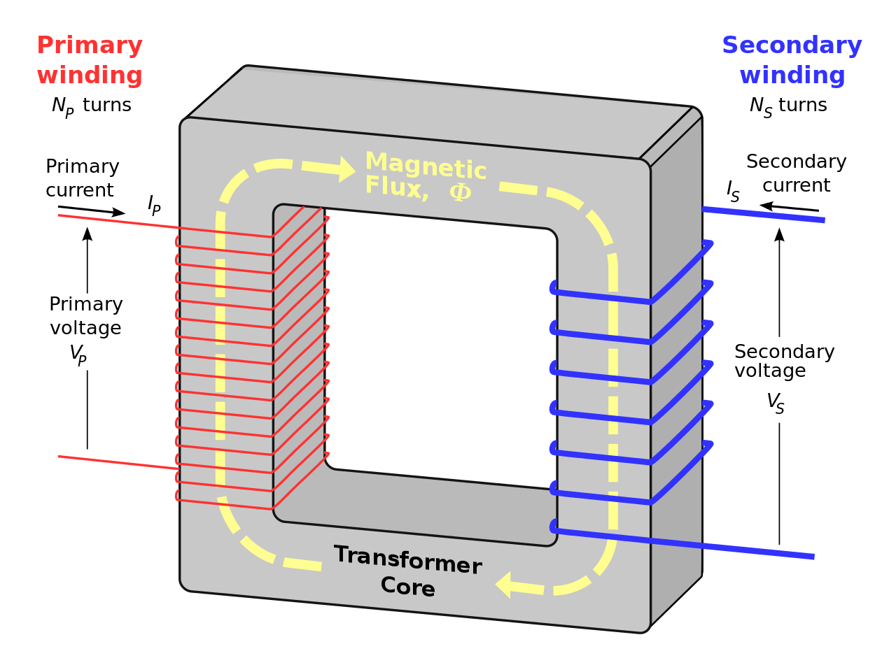
Idealised single-phase mutual inductance between the two windings results in an induced voltage on the secondary side, whose magnitude is determined by the ratio of turns between the two windings. A transformer has two coils, primary and secondary. The primary coil receives the input voltage, whereas, the secondary coil produces the output voltage.
ReferenceDaniels, A (1976). Introduction to Electrical Machines. | ||
|---|---|---|---|
| Source |
Created in Inkscape. | ||
| Date | |||
| Author |
| ||
| Permission (Reusing this file) |
See below.
|
 | I, the creator of this work, hereby grant the permission to copy, distribute and/or modify this document under the terms of the GNU Free Documentation License, Version 1.2 or any later version published by the Free Software Foundation; with no Invariant Sections, no Front-Cover Texts, and no Back-Cover Texts. Subject to disclaimers. |
| This work is licensed under the Creative Commons Attribution-ShareAlike 3.0 License. This licensing tag was added to this file as part of the GFDL licensing update. |
 | This file is a candidate to be copied to Wikimedia Commons.
Any user may perform this transfer; refer to Wikipedia:Moving files to Commons for details. If this file has problems with attribution, copyright, or is otherwise ineligible for Commons, then remove this tag and DO NOT transfer it; repeat violators may be blocked from editing. Other Instructions
| ||
| |||
File history
Click on a date/time to view the file as it appeared at that time.
| Date/Time | Thumbnail | Dimensions | User | Comment | |
|---|---|---|---|---|---|
| current | 13:16, 31 December 2005 | | 750 × 563 (35 KB) | BillC (talk | contribs) | Idealised single-phase transformer showing path of magnetic flux through the core. Created in Inkscape. {{GFDL-self}} |
You cannot overwrite this file.