Luneburg lens

A Luneburg lens (original German Lüneburg lens) is a spherically symmetric
For certain index profiles, the lens will form perfect geometrical images of two given concentric spheres onto each other. There are an infinite number of refractive-index profiles that can produce this effect. The simplest such solution was proposed by Rudolf Luneburg in 1944.[1] Luneburg's solution for the refractive index creates two conjugate foci outside the lens. The solution takes a simple and explicit form if one focal point lies at infinity, and the other on the opposite surface of the lens. J. Brown and A. S. Gutman subsequently proposed solutions which generate one internal focal point and one external focal point.[2][3] These solutions are not unique; the set of solutions are defined by a set of definite integrals which must be evaluated numerically.[4]
Designs
Luneburg's solution

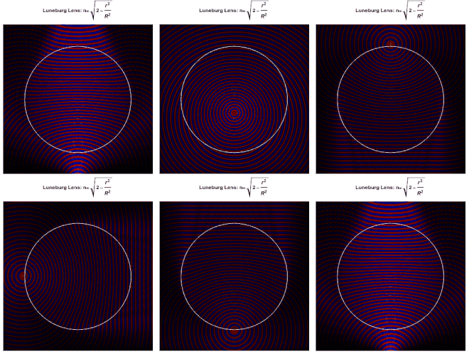
Each point on the surface of an ideal Luneburg lens is the focal point for parallel radiation incident on the opposite side. Ideally, the
where is the radius of the lens. Because the refractive index at the surface is the same as that of the surrounding medium, no reflection occurs at the surface. Within the lens, the paths of the rays are arcs of ellipses.
Maxwell's fish-eye lens

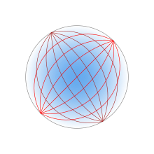
Maxwell's fish-eye lens is also an example of the generalized Luneburg lens. The fish-eye, which was first fully described by Maxwell in 1854[5] (and therefore pre-dates Luneburg's solution), has a refractive index varying according to
where is the index of refraction at the center of the lens and is the radius of the lens's spherical surface.[6] The index of refraction at the lens's surface is . The lens images each point on the spherical surface to the opposite point on the surface. Within the lens, the paths of the rays are arcs of circles.
Publication and attribution
The properties of this lens are described in one of a number of set problems or puzzles in the 1853
Applications
In practice, Luneburg lenses are normally layered structures of discrete concentric shells, each of a different refractive index. These shells form a stepped refractive index profile that differs slightly from Luneburg's solution. This kind of lens is usually employed for
Radar reflector
A radar reflector can be made from a Luneburg lens by metallizing parts of its surface. Radiation from a distant radar transmitter is focussed onto the underside of the metallization on the opposite side of the lens; here it is reflected, and focussed back onto the radar station. A difficulty with this scheme is that metallized regions block the entry or exit of radiation on that part of the lens, but the non-metallized regions result in a blind-spot on the opposite side.
Removable Luneburg lens type radar reflectors are sometimes attached to military aircraft in order to make stealth aircraft visible during training operations, or to conceal their true radar signature. Unlike other types of radar reflectors, their shape doesn't affect the handling of the aircraft.[9]
Microwave antenna

A Luneburg lens can be used as the basis of a high-gain radio antenna. This antenna is comparable to a
A Luneburg lens antenna offers a number of advantages over a parabolic dish. Because the lens is spherically symmetric, the antenna can be steered by moving the feed around the lens, without having to bodily rotate the whole antenna. Again, because the lens is spherically symmetric, a single lens can be used with several feeds looking in widely different directions. In contrast, if multiple feeds are used with a parabolic reflector, all must be within a small angle of the optical axis to avoid suffering coma (a form of de-focussing). Apart from offset systems, dish antennas suffer from the feed and its supporting structure partially obscuring the main element (aperture blockage); in common with other refracting systems, the Luneburg lens antenna avoids this problem.
A variation on the Luneburg lens antenna is the hemispherical Luneburg lens antenna or Luneburg reflector antenna. This uses just one hemisphere of a Luneburg lens, with the cut surface of the sphere resting on a reflecting metal ground plane. The arrangement halves the weight of the lens, and the ground plane provides a convenient means of support. However, the feed does partially obscure the lens when the angle of incidence on the reflector is less than about 45°.
Path of a ray within the lens
For any spherically symmetric lens, each ray lies entirely in a plane passing through the centre of the lens. The initial direction of the ray defines a line which together with the centre-point of the lens identifies a plane bisecting the lens. Being a plane of symmetry of the lens, the
Given any two points on a ray (such as the point of entry and exit from the lens),
where is the speed of light in vacuum. Minimizing this yields a second-order differential equation determining the dependence of on along the path of the ray. This type of minimization problem has been extensively studied in
where is a
The parameter is a constant for any given ray, but differs between rays passing at different distances from the centre of the lens. For rays passing through the centre, it is zero. In some special cases, such as for Maxwell's fish-eye, this first order equation can be further integrated to give a formula for as a function or . In general it provides the relative rates of change of and , which may be integrated numerically to follow the path of the ray through the lens.
See also
- Ball lens
- BLITS (Ball Lens In The Space) satellite
- Gravitational lenses also have a radially decreasing refractive index.
References
- ^ a b Luneburg, R. K. (1944). Mathematical Theory of Optics. Providence, Rhode Island: Brown University. pp. 189–213.
- ^ Brown, J. (1953). Wireless Engineer. 30: 250.
{{cite journal}}: Missing or empty|title=(help) - .
- S2CID 119949981.
- ^ a b "Solutions of problems (prob. 3, vol. VIII. p. 188)". The Cambridge and Dublin Mathematical Journal. 9. Macmillan: 9–11. 1854.
- S2CID 91184610.)
{{cite journal}}: CS1 maint: multiple names: authors list (link - ^ "Problems (3)". The Cambridge and Dublin Mathematical Journal. 8. Macmillan: 188. 1853.
- ^ Niven, ed. (1890). The Scientific Papers of James Clerk Maxwell. New York: Dover Publications. p. 76.
- ^ "Luneburg lens". www.eahison.com. Archived from the original on 2021-09-27. Retrieved 2021-04-05.
- ISBN 9780442015930.


