
Antenna array

An antenna array (or array antenna) is a set of multiple connected
An antenna array can achieve higher
The term antenna array most commonly means a driven array consisting of multiple identical
A
Principle
From the
One technique is to use reflection by large metal surfaces such as parabolic reflectors or horns, or refraction by dielectric lenses to change the direction of the radio waves, to focus the radio waves from a single low gain antenna into a beam. This type is called an aperture antenna. A parabolic dish is an example of this type of antenna.
A second technique is to use multiple antennas which are fed from the same transmitter or receiver; this is called an array antenna, or antenna array. If the currents are fed to the antennas with the proper
The
Arrays in which the antenna elements are fed in phase are broadside arrays; the main lobe is emitted perpendicular to the plane of the elements.
The largest array antennas are
-
 VHFfolded dipoles
 -
 cell phone tower. Collinear dipole arrays, radiating a flat, fan-shaped beam.
 -
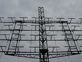 108 MHz reflective array antenna of an SCR-270 radar used during World War II consists of 32 half-wave dipole antennas in front of a reflecting screen.
 -
 US Air Force PAVE PAWS phased array 420–450 MHz radar antenna for ballistic missile detection, Alaska. The two circular arrays are each composed of 2677 crossed dipole antennas.
 -
 Some of the crossed-dipole elements in the PAVE PAWS phased array antenna, left
 -
 Batwing VHF television broadcasting antenna
 -
 Crossed-dipole FM radio broadcast antenna
 -
 Curtain array shortwave transmitting antenna, Austria. Wire dipoles suspended between towers
 -
 Turnstile antenna array used for satellite communication
 -
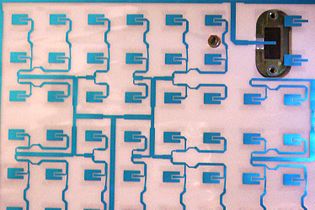 Flat microstrip array antenna for satellite TV reception.
 -
 The Very Large Array, a radio telescope made of a Y-shaped array of 27 dish antennas in Socorro, New Mexico
 -
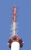
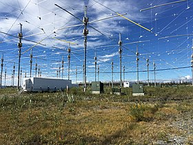 HAARP, a phased arrayof 180 crossed dipoles in Alaska which can transmit a 3.6 MW beam of 3–10 MHz radio waves into the ionosphere for research purposes
 -
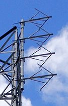
 Array of four helical antennas used as a satellite tracking antenna, Pleumeur-Bodou, France


Types
Most array antennas can be divided into two classes based on how the component antennas' axis relates to the radiation direction.
- A broadside array is a one or two dimensional array in which the direction of radiation (main lobe) of the radio waves is perpendicular to the plane of the antennas. To radiate perpendicularly, the antennas must be fed in phase.
- An endfire array is a linear array in which the direction of radiation is along the line of the antennas. The antennas must be fed with a phase difference equal to the separation of adjacent antennas.
There are also arrays (such as phased arrays) which don't belong to either of these categories, in which the direction of radiation is at some other angle to the antenna axis.
Array antennas can also be categorized by how the element antennas are arranged:
- Driven array – This is an array in which the individual component antennas are all "driven" – connected to the transmitter or receiver. The individual antennas, which are usually identical, often consist of single Yagi antennas or turnstile antennas.
- Collinear array – a broadside array consisting of multiple identical dipole antennas oriented vertically in a line. This is a high gain omnidirectional antenna, often used in the VHF band as broadcasting antennas for television stations and base station antennas for land mobile two-way radios.
- Superturnstile or Batwing array – specialized vertical antenna used for television broadcasting consisting of multiple crossed-dipole antennas mounted collinearly on a mast. High gain omnidirectional radiation pattern with wide bandwidth.
- Planar array – a flat two-dimensional array of antennas. Since an array of omnidirectional antennas radiates two beams 180° apart broadside from both sides of the antenna, it is usually either mounted in front of a flat reflector, or is composed of directive antennas such as Yagi or helicalantennas, to give a unidirectional beam.
- Reflective array – a planar array of antennas, often half-wave dipoles fed in phase, in front of a flat reflector such as a metal plate or wire screen. This radiates a single beam of radio waves perpendicular (broadside) to the array. Used as UHF television antennas and radar antennas.
- Curtain array – an outdoor wire shortwave transmitting antenna consisting of a planar array of wire dipoles suspended in front of a vertical reflector made of a "curtain" of parallel wires. Used on HF band as long distance transmitting antenna for shortwave broadcasting stations. May be steered as phased array.
- Microstrip antenna – an array of patch antennas fabricated on a printed circuit board with copper foil on the reverse side functioning as a reflector. The elements are fed through striplines made of copper foil. Used as UHF and satellite television receiving antennas.
- phase shifter, controlled by a computer. By changing the relative phase of the feed currents, the beam can instantly be pointed in different directions. Widely used in military radars, this technique is rapidly spreading to civilian applications.
- Passive Electronically Scanned Array(PESA) – A phased array as described above, in which the antenna elements are fed from a single transmitter or receiver through phase shifters.
- Active Electronically Scanned Array(AESA) – A phased array in which each antenna element has its own transmitter and/or receiver module, controlled by a central computer. This second generation phased array technology can radiate multiple beams at multiple frequencies simultaneously, and is mostly used in sophisticated military radars.
- phase shifterswhich compensate for the varying path lengths, allowing the antenna to radiate a plane wave beam. Conformal antennas are often integrated into the curving skin of aircraft and missiles, to reduce aerodynamic drag.
- phase shiftersin the feed lines, controlled by a computer.
- Collinear array – a broadside array consisting of multiple identical dipole antennas oriented vertically in a line. This is a high gain omnidirectional antenna, often used in the VHF band as broadcasting antennas for television stations and base station antennas for land mobile two-way radios.
- Log-periodic dipole array (LPDA) – an endfire array consisting of many dipole driven elements in a line, with gradually increasing length. It acts as a high gain broadband antenna. Used as television reception antennas and for shortwave communication.
- parasitic elements, are not. The parasitic elements function as resonators, absorbing radio waves from the driven element and reradiating them with a different phase, to modify the radiation pattern of the antenna, increasing the power radiated in the desired direction. Since these have only one driven element they are often called "antennas" instead of "arrays".
- UHFbands as television antennas, shortwave communication antennas, and in radar arrays.
- Quad antenna – This consists of multiple loop antennas in a line, with one driven loop and the others parasitic. Functions similarly to the Yagi antenna.
Periodic Arrays
Let us consider a linear array whose elements are arranged along the x-axis of an orthogonal Cartesian reference system. It is assumed that radiators have the same orientation and the same polarization of the electric field. Based on this, the array factor can be written as follows[4]

where is the number of antenna elements, is the wavenumber, and (in meters) are the complex excitation coefficient and the position of the n-th radiator, respectively, , with and being the zenith angle and azimuth angle, respectively. If the spacing between adjacent elements is constant, then it can be written that , and the array is said to be periodic. The array is periodic both spatially (physically) and in the variable . For example, if , with being the wavelength, then the magnitude of the array factor has a period, in the domain of , equal to . It is worth emphasising that is an auxiliary variable. In fact, from a physical point of view, the values of that are of interest for radiative purposes fall in the interval , which is associated with the values of and . In this case, the interval [-1,1] is called visible space. As shown further, if the definition of the variable changes, the extent of the visible space also changes accordingly.


![{\displaystyle [-1,1]}](https://wikimedia.org/api/rest_v1/media/math/render/svg/51e3b7f14a6f70e614728c583409a0b9a8b9de01)
Now, suppose that the excitation coefficients are positive real variables. In this case, always in the domain of , the array factor magnitude has a main lobe with maximum value at , called mainlobe, several secondary lobes lower than the mainlobe, called sidelobes and mainlobe replicas called grating-lobes. Grating lobes are a source of disadvantages in both transmission and reception. In fact, in transmission, they can lead to radiation in unwanted directions, while, in reception, they can be a source of ambiguity since the desired signal entering the mainlobe region could be strongly disturbed by other signals (unwanted interfering signals) entering the regions of the various grating lobes. Therefore, in periodic arrays, the spacing between adjacent radiators must not exceed a specific value to prevent the appearance of grating lobes (in the visible space)in the visible space), the spacing between adjacent radiators must not exceed a specific value. For example, as seen previously, the first grating lobes for occur in . So, in this case, there are no problems since, in this way, the grating lobes are outside the interval [-1,1].


Aperiodic Arrays
As seen above, when the spacing is constant between adjacent radiators, the array factor is characterized by the presence of grating lobes. In the literature, it has been amply demonstrated that to destroy the array factor's periodicity, the same array's geometry must also be made aperiodic.[5] It is possible to act on the positions of the radiators so that these positions are not commensurable with each other. Several methods have been developed to synthesize arrays in which also the positions represent further degrees of freedom (unknowns). There are both deterministic[6] and probabilistic[7][8] methodologies. Since the probabilistic theory of aperiodic arrays is a sufficiently systematised theory, with a strong general methodological basis, let us first concentrate on describing its peculiarities.
Suppose that the radiators positions, , are independent and identically distributed random variables whose support coincides with the whole array aperture. Consequently, the array factor is a stochastic process, whose mean is as follows[7]

![{\displaystyle E\left[F(u)\right]=\textstyle \int \limits _{-L/2}^{L/2}f(x)\,e^{jkxu}\,dx}](https://wikimedia.org/api/rest_v1/media/math/render/svg/5ebf0d91cd9cdeb66c749d3bff56dab8b5c38eef)
Design of antenna arrays
In an antenna array providing a fixed radiation pattern, we may consider that the feed network is a part of the antenna array. Thus, the antenna array has a single port. Narrow beams can be formed, provided the phasing of each element of the array is appropriate. If, in addition, the amplitude of the excitation received by each element (during emission) is also well chosen, it is possible to synthesize a single-port array having a radiation pattern that closely approximates a specified pattern.[4] Many methods have been developed for array pattern synthesis. Additional issues to be considered are matching, radiation efficiency and bandwidth.
The design of an electronically steerable antenna array is different, because the phasing of each element can be varied, and possibly also the relative amplitude for each element. Here, the antenna array has multiple ports, so that the subject matters of matching and efficiency are more involved than in the single-port case. Moreover, matching and efficiency depend on the excitation, except when the interactions between the antennas can be ignored.
An antenna array used for spatial diversity and/or spatial multiplexing (which are different types of MIMO radio communication) always has multiple ports.[9] It is intended to receive independent excitations during emission, and to deliver more or less independent signals during reception. Here also, the subject matters of matching and efficiency are involved, especially in the case of an antenna array of a mobile device (see chapter 10 of [9]), since, in this case, the surroundings of the antenna array influence its behavior, and vary over time. Suitable matching metrics and efficiency metrics take into account the worst possible excitations.[10]
See also
References
- ^ Poole, Ian (2016). "What is MIMO? Multiple Input Multiple Output Tutorial". Antennas and propagation. Radio-electronics.com (Adrio Communications. Retrieved February 23, 2017.
- ^ a b Bevelacqua, Peter (2016). "Array Antennas". Antenna-theory.com. Retrieved February 23, 2017.
- ^ Poole, Ian (2016). "Smart Antennas Tutorial". Antennas and propagation. Radio-electronics.com (Adrio Communications). Retrieved February 23, 2017.
- ^ ISBN 0-07-011808-6.
- ISSN 0096-1973.
- ISSN 0096-1973.
- ^ ISSN 0096-1973.
- ISSN 0096-1973.
- ^ ISBN 978-0-12-382194-2.
- .