
Bridge circuit
A bridge circuit is a
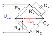
The best-known bridge circuit, the
resistance. It is constructed from four resistors, two of known values R1 and R3 (see diagram), one whose resistance is to be determined Rx, and one which is variable and calibrated R2. Two opposite vertices are connected to a source of electric current, such as a battery, and a galvanometer
is connected across the other two vertices. The variable resistor is adjusted until the galvanometer reads zero. It is then known that the ratio between the variable resistor and its neighbour R1 is equal to the ratio between the unknown resistor and its neighbour R3, which enables the value of the unknown resistor to be calculated.
The Wheatstone bridge has also been generalised to measure
potential dividers
sharing a common source.
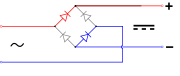
In power supply design, a bridge circuit or
bridge rectifier is an arrangement of diodes
or similar devices used to rectify an electric current, i.e. to convert it from an unknown or alternating polarity to a direct current of known polarity.
In some motor controllers, an H-bridge is used to control the direction the motor turns.
Bridge current equation

From the figure to the right, the bridge current is represented as I5
Per Thévenin's theorem, finding the Thévenin equivalent circuit which is connected to the bridge load R5 and using the arbitrary current flow I5, we have:
Thevenin Source (Vth) is given by the formula:

and the Thevenin resistance (Rth):

Therefore, the current flow (I5) through the bridge is given by Ohm's law:

and the voltage (V5) across the load (R5) is given by the voltage divider formula:

See also
- Phantom circuit - a use of balanced bridge circuits in telephony
- Lattice filter- an application of bridge topology to all-pass filters
Gallery
-

-
-

-
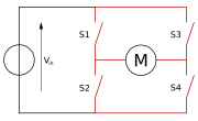 H bridge
 -

-
-

-
 Lattice bridge
 -
 Bridged T circuit
 -


_Bridge_T.svg)

References
External links
- Jim Williams, "Bridge circuits: Marrying gain and balance", Linear Technology Application Note 43, June 1990.
- Bridge circuits - Chapter 8 from an online book.
| Authority control databases: National |
|---|