
Galvanometer
This article needs additional citations for verification. (March 2009) |

A galvanometer is an
Galvanometers came from the observation, first noted by
Galvanometers have been essential for the development of science and technology in many fields. For example, in the 1800s they enabled long-range communication through submarine cables, such as the earliest
Galvanometers have also been used as the display components of other kinds of analog meters (e.g., light meters and VU meters), capturing the outputs of these meters' sensors. Today, the main type of galvanometer still in use is the D'Arsonval/Weston type.
Operation

Modern galvanometers, of the D'Arsonval/Weston type, are constructed with a small pivoting coil of wire, called a spindle, in the field of a permanent magnet. The coil is attached to a thin pointer that traverses a calibrated scale. A tiny torsion spring pulls the coil and pointer to the zero position.

When a direct current (DC) flows through the coil, the coil generates a magnetic field. This field acts against the permanent magnet. The coil twists, pushing against the spring, and moves the pointer. The hand points at a scale indicating the electric current. Careful design of the pole pieces ensures that the magnetic field is uniform so that the angular deflection of the pointer is proportional to the current. A useful meter generally contains a provision for damping the mechanical resonance of the moving coil and pointer, so that the pointer settles quickly to its position without oscillation.
The basic sensitivity of a meter might be, for instance, 100
These capabilities to translate different kinds of electric quantities into pointer movements make the galvanometer ideal for turning the output of other sensors that output electricity (in some form or another), into something that can be read by a human.
Because the pointer of the meter is usually a small distance above the scale of the meter, parallax error can occur when the operator attempts to read the scale line that "lines up" with the pointer. To counter this, some meters include a mirror along with the markings of the principal scale. The accuracy of the reading from a mirrored scale is improved by positioning one's head while reading the scale so that the pointer and the reflection of the pointer are aligned; at this point, the operator's eye must be directly above the pointer and any parallax error has been minimized.
Uses

Probably the largest use of galvanometers was of the D'Arsonval/Weston type used in analog meters in electronic equipment. Since the 1980s, galvanometer-type analog meter movements have been displaced by analog-to-digital converters (ADCs) for many uses. A digital panel meter (DPM) contains an ADC and numeric display. The advantages of a digital instrument are higher precision and accuracy, but factors such as power consumption or cost may still favor the application of analog meter movements.
Modern uses
Most modern uses for the galvanometer mechanism are in positioning and control systems. Galvanometer mechanisms are divided into moving magnet and moving coil galvanometers; in addition, they are divided into closed-loop and open-loop - or resonant - types.
Mirror galvanometer systems are used as beam positioning or beam steering elements in
Open loop, or resonant mirror galvanometers, are mainly used in some types of laser-based bar-code scanners, printing machines, imaging applications, military applications and space systems. Their non-lubricated bearings are especially of interest in applications that require functioning in a high vacuum.

Moving coil type galvanometer mechanisms (called 'voice coils' by hard disk manufacturers) are used for controlling the head positioning servos in hard disk drives and CD/DVD players, in order to keep mass (and thus access times), as low as possible.
Past uses
A major early use for galvanometers was for finding faults in telecommunications cables. They were superseded in this application late in the 20th century by time-domain reflectometers.
Galvanometer mechanisms were also used to get readings from photoresistors in the metering mechanisms of film cameras (as seen in the adjacent image).
In analog strip
History
Hans Christian Ørsted
The deflection of a
Schweigger and Ampère
The earliest galvanometer was reported by
Poggendorff and Thomson
.jpg)
Originally, the instruments relied on the Earth's magnetic field to provide the restoring force for the compass needle. These were called "tangent" galvanometers and had to be oriented before use. Later instruments of the "astatic" type used opposing magnets to become independent of the Earth's field and would operate in any orientation.
An early
Georg Ohm
The ability to measure voltage and current quantitatively allowed Georg Ohm, in 1827, to formulate Ohm's law – that the voltage across a conductor is directly proportional to the current through it.
D'Arsonval and Deprez
The early moving-magnet form of galvanometer had the disadvantage that it was affected by any magnets or iron masses near it, and its deflection was not linearly proportional to the current. In 1882 Jacques-Arsène d'Arsonval and Marcel Deprez developed a form with a stationary permanent magnet and a moving coil of wire, suspended by fine wires which provided both an electrical connection to the coil and the restoring torque to return to the zero position. An iron tube between the magnet's pole pieces defined a circular gap through which the coil rotated. This gap produced a consistent, radial magnetic field across the coil, giving a linear response throughout the instrument's range. A mirror attached to the coil deflected a beam of light to indicate the coil position. The concentrated magnetic field and delicate suspension made these instruments sensitive; d'Arsonval's initial instrument could detect ten microamperes.[4]
Edward Weston


Edward Weston extensively improved the design of the galvanometer. He substituted the fine wire suspension with a pivot and provided restoring torque and electrical connections[further explanation needed] through spiral springs rather than through the traditional wristwatch balance wheel hairspring. He developed a method of stabilizing the magnetic field of the permanent magnet, so the instrument would have consistent accuracy over time. He replaced the light beam and mirror with a knife-edge pointer that could be read directly. A mirror under the pointer, in the same plane as the scale, eliminated parallax observation error. To maintain the field strength, Weston's design used a very narrow circumferential slot through which the coil moved, with a minimal air-gap. This improved linearity of pointer deflection with respect to coil current. Finally, the coil was wound on a light-weight form made of conductive metal, which acted as a damper. By 1888, Edward Weston had patented and brought out a commercial form of this instrument, which became a standard electrical equipment component. It was known as a "portable" instrument because it was affected very little by mounting position or by transporting it from place to place. This design is almost universally used in moving-coil meters today.[citation needed]
Initially, laboratory instruments relying on the Earth's own magnetic field to provide restoring force for the pointer, galvanometers were developed into compact, rugged, sensitive portable instruments essential to the development of electro-technology.
Taut-band movement
The taut-band movement is a modern development of the D'Arsonval-Weston movement. The jewel pivots and hairsprings are replaced by tiny strips of metal under tension. Such a meter is more rugged for field use.[5][6]
Types
There is broadly two types of galvanometers. Some galvanometers use a solid pointer on a scale to show measurements; other very sensitive types use a miniature mirror and a beam of light to provide mechanical amplification of low-level signals.
Tangent galvanometer
A tangent galvanometer is an early
A tangent galvanometer consists of a coil of insulated copper wire wound on a circular non-magnetic frame. The frame is mounted vertically on a horizontal base provided with levelling screws. The coil can be rotated on a vertical axis passing through its centre. A compass box is mounted horizontally at the centre of a circular scale. It consists of a tiny, powerful magnetic needle pivoted at the centre of the coil. The magnetic needle is free to rotate in the horizontal plane. The circular scale is divided into four quadrants. Each quadrant is graduated from 0° to 90°. A long thin aluminium pointer is attached to the needle at its centre and at right angle to it. To avoid errors due to parallax, a plane mirror is mounted below the compass needle.
In operation, the instrument is first rotated until the magnetic field of the Earth, indicated by the compass needle, is parallel with the plane of the coil. Then the unknown current is applied to the coil. This creates a second magnetic field on the axis of the coil, perpendicular to the Earth's magnetic field. The compass needle responds to the
- Tangent Galvanometer
-
 An 1850 Pouillet Tangent Galvanometer on display at Musée d'histoire des sciences de la Ville de Genève
 -
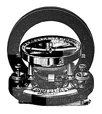 Tangent galvanometer made by J. H. Bunnell Co. around 1890.
 -
 Top view of a tangent galvanometer made about 1950. The indicator needle of the compass is perpendicular to the shorter, black magnetic needle.


Theory
The galvanometer is oriented so that the plane of the coil is vertical and aligned along parallel to the horizontal component BH of the Earth's magnetic field (i.e. parallel to the local "magnetic meridian"). When an electric current flows through the galvanometer coil, a second magnetic field B is created. At the center of the coil, where the compass needle is located, the coil's field is perpendicular to the plane of the coil. The magnitude of the coil's field is:

where I is the current in

From tangent law, B = BH tan θ, i.e.

or

or I = K tan θ, where K is called the Reduction Factor of the tangent galvanometer.
One problem with the tangent galvanometer is that its resolution degrades at both high currents and low currents. The maximum resolution is obtained when the value of θ is 45°. When the value of θ is close to 0° or 90°, a large percentage change in the current will only move the needle a few degrees.[12]
Geomagnetic field measurement
A tangent galvanometer can also be used to measure the magnitude of the horizontal component of the
Astatic galvanometer
Unlike the tangent galvanometer, the astatic galvanometer does not use the Earth's magnetic field for measurement, so it does not need to be oriented with respect to the Earth's field, making it easier to use. Developed by
- Nobili's astatic galvanometer
-
 Galvanometer on display at Musée d'histoire des sciences de la Ville de Genève
 -
 Detail of an astatic galvanometer.


Mirror galvanometer
To achieve higher sensitivity to detect extremely small currents, the
Ballistic galvanometer
A ballistic galvanometer is a type of sensitive galvanometer for measuring the quantity of charge discharged through it. It is an integrator, by virtue of the long time constant of its response, unlike a current-measuring galvanometer. The moving part has a large moment of inertia that gives it an oscillation period long enough to make the integrated measurement. It can be either of the moving coil or moving magnet type; commonly it is a mirror galvanometer.
See also
References
- ^ Schiffer, Michael Brian. (2008)"Electromagnetism Revealed," Power Struggles: Scientific Authority and the Creation of Practical Electricity Before Edison. Page 24.
- ^ "Schweigger Multiplier – 1820". Maglab. National High Magnetic Field Laboratory. Retrieved 17 October 2017.
- ISBN 0309167825
- ISBN 0-7803-1193-0.
- ^ Weschler Instruments (20 February 2020). "The taut-band analog meter". Retrieved 25 April 2020.
- ^ "Dictionary Central". Archived from the original on 18 June 2018. Retrieved 18 June 2018.
- ^ Nervander, J.J. (1834). "Mémoire sur un Galvanomètre à châssis cylindrique par lequel on obtient immédiatement et sans calcul la mesure de l'intensité du courant électrique qui produit la déviation de l'aiguille aimantée" [Memoir on a cylindrical-frame galvanometer by which one obtains immediately and without calculation the measurement of the intensity of the electric current which produces the deflection of the magnetic needle]. Annales de Chimie et de Physique (Paris) (in French). 55: 156–184.
- ^ Pouillet, Claude (1837). "Mémoire sur la pile de Volta et sur la loi générale de l'intensité que prennent les courrants, soit qu'ils proviennent d'un seul élément, soit qu'ils proviennent d'une pile à grande ou à petite tension" [Memoir on the Voltaic pile [i.e., battery] and on the general law of the intensity that currents assume, whether they come from a single element or they come from a pile of high or low voltage]. Comptes rendus hebdomadaires des séances de l'Académie des sciences (in French). 4: 267–279.
- .
- S2CID 27081490.
- ^ Greenslade Jr., Thomas B. "Tangent Galvanometer". Kenyon College. Retrieved 26 April 2016.
- ^ "Theory". GALVANOMETER. Retrieved 5 April 2017.
- ^ Nobili, Leopoldo (1825). "Sur un nouveau galvanomètre présenté à l'Académie des Sciences" [On a new galvanometer presented at the Academy of Sciences]. Bibliothèque universelle (in French). 29: 119–125.
- ^ Greenslade, Thomas B. Jr. "Instruments for Natural Philosophy — Astatic Galvanometer". Kenyon College. Retrieved 6 November 2019.
External links
- Galvanometer - Interactive Java Tutorial National High Magnetic Field Laboratory
- Selection of historic galvanometer in the Virtual Laboratory of the Max Planck Institute for the History of Science
- The History Corner: The Galvanometer by Nick Joyce and David Baker, April 1, 2008, Ass. of Physological Science. Retrieved February 26, 2022.