
Pulley
| Pulley | |
|---|---|
 Pulleys on a ship. In this context, pulleys are normally known as blocks. | |
| Classification | Simple machine |
| Industry | Construction, transportation |
| Wheels | 1 |
| Axles | 1 |

A pulley is a wheel on an axle or shaft enabling a taut cable or belt passing over the wheel to move and change direction, or transfer power between itself and a shaft. A sheave or pulley wheel is a pulley using an axle supported by a frame or shell (block) to guide a cable or exert force.
A pulley may have a
The earliest evidence of pulleys dates back to
Block and tackle

A block is a set of pulleys (wheels) assembled so that each pulley rotates independently from every other pulley. Two blocks with a rope attached to one of the blocks and threaded through the two sets of pulleys form a block and tackle.[8] [9]
A
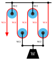
In the diagram on the right, the ideal mechanical advantage of each of the block and tackle assemblies[7] shown is as follows:
- Gun tackle: 2
- Luff tackle: 3
- Double tackle: 4
- Gyn tackle: 5
- Threefold purchase: 6
Rope and pulley systems


A rope and pulley system—that is, a block and tackle—is characterised by the use of a single continuous rope to transmit a tension force around one or more pulleys to lift or move a load—the rope may be a light line or a strong cable. This system is included in the list of simple machines identified by Renaissance scientists.[10][11]
If the rope and pulley system does not dissipate or store energy, then its mechanical advantage is the number of parts of the rope that act on the load. This can be shown as follows.
Consider the set of pulleys that form the moving block and the parts of the rope that support this block. If there are p of these parts of the rope supporting the load W, then a force balance on the moving block shows that the tension in each of the parts of the rope must be W/p. This means the input force on the rope is T=W/p. Thus, the block and tackle reduces the input force by the factor p.
-
 A gun tackle has a single pulley in both the fixed and moving blocks with two rope parts supporting the load W.
 -
 Separation of the pulleys in the gun tackle show the force balance that results in a rope tension of W/2.


-
 A double tackle has two pulleys in both the fixed and moving blocks with four rope parts supporting the load W.
 -
 Separation of the pulleys in the double tackle show the force balance that results in a rope tension of W/4.


Method of operation
The simplest theory of operation for a pulley system assumes that the pulleys and lines are weightless and that there is no energy loss due to friction. It is also assumed that the lines do not stretch.
In equilibrium, the forces on the moving block must sum to zero. In addition the tension in the rope must be the same for each of its parts. This means that the two parts of the rope supporting the moving block must each support half the load.
-
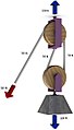
 Fixed pulley
 -
 Diagram 1: The load F on the moving pulley is balanced by the tension in two parts of the rope supporting the pulley.
 -
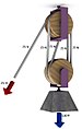
 Movable pulley
 -
 Diagram 2: A movable pulley lifting the load W is supported by two rope parts with tension W/2.


These are different types of pulley systems:
- Fixed: A fixed pulley has an axle mounted in bearings attached to a supporting structure. A fixed pulley changes the direction of the force on a rope or belt that moves along its circumference. Mechanical advantage is gained by combining a fixed pulley with a movable pulley or another fixed pulley of a different diameter.
- Movable: A movable pulley has an axle in a movable block. A single movable pulley is supported by two parts of the same rope and has a mechanical advantage of two.
- Compound: A combination of fixed and movable pulleys forms a block and tackle. A block and tackle can have several pulleys mounted on the fixed and moving axles, further increasing the mechanical advantage.
-
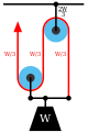 Diagram 3: The gun tackle "rove to advantage" has the rope attached to the moving pulley. The tension in the rope is W/3 yielding an advantage of three.
 -
 Diagram 3a: The Luff tackle adds a fixed pulley "rove to disadvantage." The tension in the rope remains W/3 yielding an advantage of three.


The mechanical advantage of the gun tackle can be increased by interchanging the fixed and moving blocks so the rope is attached to the moving block and the rope is pulled in the direction of the lifted load. In this case the block and tackle is said to be "rove to advantage."[12] Diagram 3 shows that now three rope parts support the load W which means the tension in the rope is W/3. Thus, the mechanical advantage is three.
By adding a pulley to the fixed block of a gun tackle the direction of the pulling force is reversed though the mechanical advantage remains the same, Diagram 3a. This is an example of the Luff tackle.
Free body diagrams
The

The ratio of the load to the input tension force is the mechanical advantage MA of the pulley system,[13]

Thus, the mechanical advantage of the system is equal to the number of sections of rope supporting the load.
Belt and pulley systems


A belt and pulley system is characterized by two or more pulleys in common to a belt. This allows for mechanical power, torque, and speed to be transmitted across axles. If the pulleys are of differing diameters, a mechanical advantage is realized.
A belt drive is analogous to that of a chain drive; however, a belt sheave may be smooth (devoid of discrete interlocking members as would be found on a chain sprocket, spur gear, or timing belt) so that the mechanical advantage is approximately given by the ratio of the pitch diameter of the sheaves only, not fixed exactly by the ratio of teeth as with gears and sprockets.
In the case of a drum-style pulley, without a groove or flanges, the pulley often is slightly convex to keep the
Just as the diameters of
With belts and pulleys, friction is one of the most important forces. Some uses for belts and pulleys involve peculiar angles (leading to bad belt tracking and possibly slipping the belt off the pulley) or low belt-tension environments, causing unnecessary slippage of the belt and hence extra wear to the belt. To solve this, pulleys are sometimes lagged. Lagging is the term used to describe the application of a coating, cover or wearing surface with various textured patterns which is sometimes applied to pulley shells. Lagging is often applied in order to extend the life of the shell by providing a replaceable wearing surface or to improve the friction between the belt and the pulley. Notably drive pulleys are often rubber lagged (coated with a rubber friction layer) for exactly this reason.[15]
See also
References
- ISBN 9780195113747.
- ISBN 9781575060422.
- ISBN 0-486-25593-X.
- ISBN 978-0-19-537123-9.
- ISBN 978-0-13-516062-6.
- ISBN 9783319580593.
- ^ ISBN 978-0-07-149301-7.
- ^ Prater, Edward L. (1994). "Basic Machines" (PDF). Naval Education and Training Professional Development and Technology Center, NAVEDTRA 14037.
- ISBN 0-486-21709-4. Archived from the original(PDF) on 2016-09-22. Retrieved 2011-12-13.
- ^ Avery, Elroy (1878). Elementary physics. Sheldon and company. p. 459.
wheel and axle.
- ^ Bowser, Edward (1890). An elementary treatise on analytic mechanics: With numerous examples (5 ed.). D. Van Nostrand company. p. 180.
- ^ "Seamanship Reference, Chapter 5, General Rigging" (PDF). sccheadquarters.com.
- OCLC 892430550.
- ^ "How crowned pulleys keep a flat belt tracking". Wood Gears.
- ^ "Pulley Lagging". CKIT. Retrieved 17 June 2022.