
Directional antenna

A directional antenna or beam antenna is an
The extent to which an antenna's angular distribution of radiated power, its
In contrast, a low-gain antenna (LGA) is an omnidirectional antenna, with a broad radiowave beam width, that allows the signal to propagate reasonably well even in mountainous regions and is thus more reliable regardless of terrain. Low-gain antennas are often used in spacecraft as a backup to the high-gain antenna, which transmits a much narrower beam and is therefore susceptible to loss of signal.[3]
All practical antennas are at least somewhat directional, although usually only the direction in the plane parallel to the earth is considered, and practical antennas can easily be omnidirectional in one plane. The most common directional antenna types are[citation needed]
- the Yagi-Uda antenna,
- the log-periodic antenna, and
- the corner reflector antenna.
These antenna types, or combinations of several single-frequency versions of one type or (rarely) a combination of two different types, are frequently sold commercially as residential
Principle of operation
When transmitting, a high-gain antenna allows more of the transmitted power to be sent in the direction of the receiver, increasing the received signal strength. When receiving, a high gain antenna captures more of the signal, again increasing signal strength. Due to reciprocity, these two effects are equal—an antenna that makes a transmitted signal 100 times stronger (compared to an isotropic radiator) will also capture 100 times as much energy as the isotropic antenna when used as a receiving antenna. As a consequence of their directivity, directional antennas also send less (and receive less) signal from directions other than the main beam. This property may avoid interference from other out-of-beam transmitters, and always reduces antenna noise. (Noise comes from every direction, but a desired signal will only come from one approximate direction, so the narrower the antenna's beam, the better the crucial signal-to-noise ratio.)
There are many ways to make a high-gain antenna; the most common are
Antenna gain
Antenna gain can also be measured in dBd, which is gain in
Gain is also dependent on the number of elements and the tuning of those elements. Antennas can be tuned to be resonant over a wider spread of frequencies but, all other things being equal, this will mean the gain of the aerial is lower than one tuned for a single frequency or a group of frequencies. For example, in the case of wideband TV antennas the fall off in gain is particularly large at the bottom of the TV transmitting band. In the UK this bottom third of the TV band is known as group A.[5]
Other factors may also affect gain such as aperture (the area the antenna collects signal from, almost entirely related to the size of the antenna but for small antennas can be increased by adding a ferrite rod), and efficiency (again, affected by size, but also resistivity of the materials used and impedance matching). These factors are easy to improve without adjusting other features of the antennas or coincidentally improved by the same factors that increase directivity, and so are typically not emphasized.
Applications
High gain antennas are typically the largest component of deep space probes, and the highest gain radio antennas are physically enormous structures, such as the
Use of high gain and
Gallery
-
 An early example (1922) of a directional AM radio transmitter using a long wire antenna, built for WOR, then in Newark, New Jersey and targeting both New York City and Philadelphia in addition to Newark.
 -
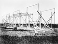 Holmdel, New Jersey, which was the world's first radio telescope, discovering radio emissions from the Milky Way.
 -
 Grote Reber's homemade antenna in Wheaton, Illinois (1937), world's second radio telescope and first parabolic radio telescope
 -
![Holmdel Horn Antenna in Holmdel, New Jersey (1960s). Built to support the Echo satellite communication program,[7] it was later used in experiments that revealed the Cosmic microwave background permeating the universe.[8]](//upload.wikimedia.org/wikipedia/commons/thumb/f/f7/Horn_Antenna-in_Holmdel%2C_New_Jersey_-_restoration1.jpg/120px-Horn_Antenna-in_Holmdel%2C_New_Jersey_-_restoration1.jpg) Echo satellite communication program,[7] it was later used in experiments that revealed the Cosmic microwave background permeating the universe.[8]
Echo satellite communication program,[7] it was later used in experiments that revealed the Cosmic microwave background permeating the universe.[8] -
 Parabolic antenna – the 70 m antenna at Goldstone Deep Space Communications Complex in the Mojave Desert, California
 -
 Voyager 2 spacecraft. The HGA (a parabolic antenna) is the large bowl-shaped object.
 -
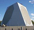 A giantphased-arrayradar in Alaska
 -
 AYagi-Uda antenna. From left to right, the elements mounted on the boom are called the reflector, driven element, and director. The reflector is easily identified as being a bit longer (5% or more) than all the other elements, and the director(s) a bit shorter (5% or more).


![Holmdel Horn Antenna in Holmdel, New Jersey (1960s). Built to support the Echo satellite communication program,[7] it was later used in experiments that revealed the Cosmic microwave background permeating the universe.[8]](/File:Horn_Antenna-in_Holmdel,_New_Jersey_-_restoration1.jpg)


See also
- Amateur radio direction finding
- Antenna boresight
- Antenna gain
- Cantenna
- Cardioid
- Cassegrain antenna
- Cassegrain reflector
- Directivity
- Loop antenna
- Omnidirectional antenna
- Parabolic antenna
- Phased array
- Radio direction finder
- Radio propagation model, Antenna subsection
- Radiation pattern
References
- ^ "Low-gain antenna". Oxford Reference (oxfordreference.com).
- ^ "Low gain aerial acceptance angle". Row ridge TX. aerialsandtv.com.
- ^ For comparison of groups of aerials to a wideband aerial of the same size / model, see "Gain graph". aerialsandtv.com.
- S2CID 2285688.
- .
- ^ "Horn antenna". Astronomy and astrophysics. History. U.S. National Park Service. 2001-11-05. Archived from the original on 2008-05-12. Retrieved 2008-05-23.
External links
- "What are high and low gain?". qrg.northwestern.edu. Communications. Evanston, IL: Northwestern University.