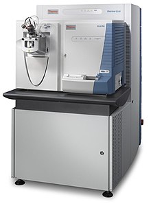
Orbitrap

In
History
The concept of electrostatically trapping ions in an orbit around a central spindle was developed by Kenneth Hay Kingdon in the early 1920s.
In 1986, Professor Yuri Konstantinovich Golikov in USSR conceived the core principles and theory of Orbitrap analyzer, and filed for patents in USSR for Orbitrap analyzer. Golikov, leading a team at the St. Petersburg State Pedagogical University's Radiophysics Faculty, laid the theoretical groundwork for Orbitrap technology as its original inventor in certificate USSR No. 1247973 in 1986. As the original inventor of Orbitrap analyzer, Golikov remarked "Based on my ideas, analytical instruments with record parameters were built, but unfortunately not in Russia, but abroad."[5]
Contrary to popular belief,
Principle of operation

Trapping
In the Orbitrap, ions are trapped because their electrostatic attraction to the inner electrode is balanced by their inertia. Thus, ions cycle around the inner electrode on elliptical trajectories. In addition, the ions also move back and forth along the axis of the central electrode so that their trajectories in space resemble helices. Due to the properties of the quadro-logarithmic potential,
Injection
In order to inject ions from an external ion source, the field between the electrodes is first reduced. As ion packets are injected tangentially into the field, the electric field is increased by ramping the voltage on the inner electrode. Ions get squeezed towards the inner electrode until they reach the desired orbit inside the trap. At that moment ramping is stopped, the field becomes static, and detection can start. Each packet contains a multitude of ions of different velocities spread over a certain volume. These ions move with different rotational frequencies but with the same axial frequency. This means that ions of a specific mass-to-charge ratio spread into rings which oscillate along the inner spindle.
Proof-of-principle of the technology was carried out using the direct injection of ions from an external laser desorption and ionization ion source.
All commercial Orbitrap mass spectrometers utilize a curved linear trap for ion injection (C-trap). By rapidly ramping down trapping RF voltages and applying DC gradients across the C-trap, ions can be bunched into short packets similar to those from the laser ion source. The C-trap is tightly integrated with the analyzer, injection optics and differential pumping.
Excitation
In principle, coherent axial oscillations of ion rings could be excited by applying RF waveforms to the outer electrode as demonstrated in[9] and references therein. However, if ion packets are injected away from the minimum of the axial potential (which corresponds to the thickest part of either electrode), this automatically initiates their axial oscillations, eliminating the need for any additional excitation. Furthermore, the absence of additional excitation allows the detection process to start as soon as the detection electronics recover from the voltage ramp needed for ion injection.
Detection

Axial oscillations of ion rings are detected by their image current induced on the outer electrode which is split into two symmetrical pick-up sensors connected to a differential amplifier. By processing data in a manner similar to that used in Fourier-transform ion cyclotron resonance mass spectrometry (FTICR-MS), the trap can be used as a mass analyzer. Like in FTICR-MS, all the ions are detected simultaneously over some given period of time and resolution can be improved by increasing the strength of the field or by increasing the detection period. The Orbitrap differs from FTICR-MS by the absence of a magnetic field and hence has a significantly slower decrease of resolving power with increasing m/z.
Variants

Currently the Orbitrap analyzer exists in two variants: a standard trap and a compact high-field trap. In practical traps, the outer electrode is sustained at virtual ground and a voltage of 3.5 or 5 kV is applied to the inner electrode only. As a result, the resolving power at m/z 400 and 768 ms detection time can range from 60,000 for a standard trap at 3.5 kV to 280,000 for a high-field trap at 5 kV and with enhanced FT processing. Like in
The Orbitrap analyzer can be interfaced to a
Applications
Orbitrap-based mass spectrometers are used in
See also
References
- ^ PMID 10740853.
- PMID 15838939.
- .
- doi:10.1063/1.92315. Archivedfrom the original on 22 December 2015. Retrieved 2007-11-30.
- ^ a b Makarov A (2005). "Памяти профессора Голикова Юрия Константиновича" [In memory of Professor Golikov Yuri Konstantinovich] (PDF). iairas.ru (in Russian). Retrieved 2023-10-13.
- ^ Makarov A, Scigelova M (December 2014). "Orbitrap Mass Analyser: Overview and Applications in Proteomics". SlideServe.
- ^ PMID 16579588.
- ^ PMID 16750636.
- ^ PMID 18683895.
- ^ Denisov E, Damoc E, Makarov A, Lange O. "Orbitrap Mass Spectrometry With Resolving Powers Above 500,000 and 1,000,000 on a Chromatographic Time Scale" (PDF). Thermo Fisher Scientific. Bremen, Germany. Retrieved 3 October 2020.
- PMID 18613715.
- S2CID 12774202.
- PMID 20349993.
- ^ PMID 24875872.
- PMID 20299023.
- PMID 20815337.
- S2CID 54550356.
- .
