Frequency response
This introduction and first section needs additional citations for verification. (August 2011) |
In
The frequency response characterizes systems in the frequency domain, just as the impulse response characterizes systems in the time domain. In linear systems (or as an approximation to a real system neglecting second order non-linear properties), either response completely describes the system and thus have one-to-one correspondence: the frequency response is the Fourier transform of the impulse response. The frequency response allows simpler analysis of cascaded systems such as multistage amplifiers, as the response of the overall system can be found through multiplication of the individual stages' frequency responses (as opposed to convolution of the impulse response in the time domain). The frequency response is closely related to the transfer function in linear systems, which is the Laplace transform of the impulse response. They are equivalent when the real part of the transfer function's complex variable is zero.[2]
Measurement and plotting

Measuring the frequency response typically involves exciting the system with an input signal and measuring the resulting output signal, calculating the
Several methods using different input signals may be used to measure the frequency response of a system, including:
- Applying constant amplitude sinusoids stepped through a range of frequencies and comparing the amplitude and phase shift of the output relative to the input. The frequency sweep must be slow enough for the system to reach its steady-stateat each point of interest
- Applying an impulse signal and taking the Fourier transform of the system's response
- Applying a power spectral density) should be used if phase information is required
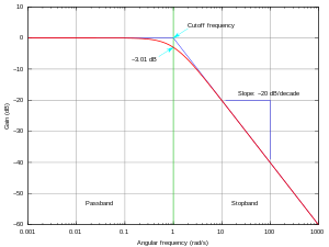
The frequency response is characterized by the magnitude, typically in
There are three common ways of plotting response measurements:
- Bode plots graph magnitude and phase against frequency on two rectangular plots
- parametricallyagainst frequency in polar form
- Nichols plots graph magnitude and phase parametrically against frequency in rectangular form
For the design of control systems, any of the three types of plots may be used to infer closed-loop stability and stability margins from the open-loop frequency response. In many frequency domain applications, the phase response is relatively unimportant and the magnitude response of the Bode plot may be all that is required. In digital systems (such as
Nonlinear frequency response
If the system under investigation is
Applications
In the audible range frequency response is usually referred to in connection with
Frequency response curves are often used to indicate the accuracy of electronic components or systems.[5] When a system or component reproduces all desired input signals with no emphasis or attenuation of a particular frequency band, the system or component is said to be "flat", or to have a flat frequency response curve.[5] In other case, we can be use 3D-form of frequency response surface.
Frequency response requirements differ depending on the application.[6] In high fidelity audio, an amplifier requires a flat frequency response of at least 20–20,000 Hz, with a tolerance as tight as ±0.1 dB in the mid-range frequencies around 1000 Hz; however, in telephony, a frequency response of 400–4,000 Hz, with a tolerance of ±1 dB is sufficient for intelligibility of speech.[6]
Once a frequency response has been measured (e.g., as an impulse response), provided the system is
The form of a frequency response curve is very important for anti-jamming protection of radars, communications and other systems.
Frequency response analysis can also be applied to biological domains, such as the detection of hormesis in repeated behaviors with opponent process dynamics,[7] or in the optimization of drug treatment regimens.[8]
See also
References
- Notes
- ISBN 978-0966017632.
- ISBN 978-1-4832-5938-3.
- ^ L. R. Rabiner and B. Gold. Theory and Application of Digital Signal Processing. – Englewood Cliffs, NJ: Prentice-Hall, 1975. – 720 pp
- ^ Billings S.A. "Nonlinear System Identification: NARMAX Methods in the Time, Frequency, and Spatio-Temporal Domains". Wiley, 2013
- ^ a b Stark, 2002, p. 51.
- ^ a b Luther, 1999, p. 141.
- ISSN 2513-0390.
- PMID 29193852.
- Bibliography
- Luther, Arch C.; Inglis, Andrew F. Video engineering, McGraw-Hill, 1999. ISBN 0-07-135017-9
- Stark, Scott Hunter. Live Sound Reinforcement, Vallejo, California, Artistpro.com, 1996–2002. ISBN 0-918371-07-4
- L. R. Rabiner and B. Gold. Theory and Application of Digital Signal Processing. – Englewood Cliffs, NJ: Prentice-Hall, 1975. – 720 pp
External links
- University of Michigan: Frequency Response Analysis and Design Tutorial Archived 2012-10-17 at the Wayback Machine
- Smith, Julius O. III: Introduction to Digital Filters with Audio Applications has a nice chapter on Frequency Response


