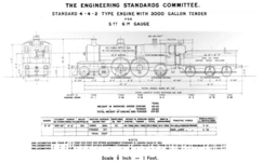
Indian locomotive class AP
| BESA AP | |
|---|---|
North Western Railway |
The AP series was a wide-gauge tender steam locomotive for passenger train service on the railways in British India, which was built around 1907. She is one of the BESA locomotives developed by the British Engineering Standards Committee, later called the British Engineering Standards Association (BESA). The abbreviation AP stands for Atlantic Passenger Locomotive, where Atlantic refers to the axle arrangement of the same name.
History
The AP series was the locomotive intended for express trains, which was first introduced in the second edition of the BESA standard from 1907. She could be equipped with three different large tenders - the small one held 3,000, the medium 4,000 and the large 4,500 gallons of water.
Vulcan delivered a series of 28 to the East Indian Railway (EIR), whose route network expanded from Calcutta towards the West. The elegant locomotives, built according to British designs, were used in front of express trains. On the railway they were numbered 1300 to 1327, the factory numbers were 2330–2357/1908.[1]
Ten locomotives were delivered to the EIR by North British Locomotive Company in 1908, and a further 8 in 1909.[2][3]
The Eastern Bengal Railway received 5 from Kitson and Company in 1908, and another two in 1909.[4] They were joined in 1930 by five locomotives that had been built by Kitson for the North Western Railway in 1908.[5]
At partition, four of the EBR locomotives went to East Pakistan, and eight to India.[6] Of the 14 remaining EIR locomotives, six went to the Eastern Railway Zone, and the other eight went to the Northern Railway Zone.[7]
-
Variant with 3000 gallon tender
-
Variant with 4000 gallon tender
-
Variant with 4500 gallon tender
Technology
The locomotive was a two-cylinder saturated steam engine with a Belpaire boiler. The grate was arranged between the coupling gear sets. The two steam cylinders were located on the outside of the frame cheeks of the inner frame, and the Walschaerts valve gear was arranged between the frames. The circulating plate was set low so that wheel protection boxes were arranged above the two coupling wheel sets. A small cow catcher was attached to the front buffer beam . The BESA standard suggested a completely enclosed cab, with the rear wall of the cab being formed by the tender. However, the locomotives built for the East Indian Railway had tenders without a rear wall of the cab. The tenders for 3000 and 4000 gallons of water were three-axle, the 4500 gallon tender was four-axle with two bogies . The two three-axle variants had running boards and handrails along the side walls, which made it possible to reach the train from the locomotive while it was moving.[8] Another peculiarity of the design was the riser arranged in the middle of the dome axes. The series had the largest wheels of any steam locomotive used in India. They were almost two meters in diameter.
Similar series

Locomotive No. 992 of the EM series on display at the National Rail Museum of India in New Delhi has very similar main dimensions to the AP series locomotives. However, it was created by converting a 2'B locomotive from the E1 series of the Great Indian Peninsula Railway (GIPR), to which a trailing axle with an external frame was added. With a diameter of 6 ft 6 in, the driving wheels have the same dimensions as those of the AP series. The drive wheels, which are also very close together, are characteristic.
External links
References
- ^ Historical Railway Images (2019-02-05). "Vulcan Foundry: Steam Locomotives Catalogue". Retrieved 2020-08-27.
- ^ "East Indian Railway Class AP steam locomotive Nr. 120". Historical Railway Images. Retrieved 2020-08-26.
- ^ Hughes (1990), p. 42.
- ^ Hughes (1990), pp. 34, 35, 38.
- ^ Hughes (1990), pp. 35, 51.
- ^ Hughes & (1990), pp. 38.
- ^ Hughes (1990), pp. 51.
- ^ can be seen on the work picture of the EIR 1300 and the drawings
- Hughes, Hugh (1990). Indian Locomotives: Part 1 – Broad Gauge 1851–1940. Harrow, Middlesex: The Continental Railway Circle. pp. 34, 35, 38, 42, 51, 78, 83, 108. OCLC 21871114.


