
Circulator
In

Theory of operation
Microwave circulators rely on the
In the

where (neglecting damping)


MHz / Oe is the effective gyromagnetic ratio and , the so-called effective g-factor, is a ferrite material constant typically in the range of 1.5 - 2.6, depending on the particular ferrite material. is the frequency of the RF/microwave signal propagating through the ferrite, is the internal magnetic bias field, and is the magnetization of the ferrite material.


In junction circulators and differential phase shift circulators, microwave signal propagation is usually orthogonal to the static magnetic bias field in the ferrite. This is the so-called transverse field case. The microwave propagation constants for this case, neglecting losses are[3]


where is the


Types
Microwave circulators fall into two main classes: differential phase shift circulators and junction circulators, both of which are based on cancellation of waves propagating over two different paths in or near magnetized ferrite material. Waveguide circulators may be of either type, while more compact devices based on
Junction circulators
Stripline junction circulators

A stripline junction circulator contains a resonator, which is located at the central junction of the
If losses are neglected for simplification, the counter-rotating modes must differ in phase by an integer multiple of for signal propagation from port 1 to port 2 (or from port 2 to port 3, or from port 3 to port 1):[6]


and similarly, for the remaining port (port 3 if signal propagation is from port 1 to port 2) to be nulled,

where is the path length between adjacent ports and and are integers. Solving the two preceding equations simultaneously, for proper circulation the necessary conditions are


and

Each of the two counter-rotating modes has its own resonant frequency.[5] The two resonant frequencies are known as the split frequencies. The circulator operating frequency is set between the two split frequencies.
These circulator types operate based on faraday rotation. Wave cancellation occurs when waves propagate with and against the circulator's direction of circulation. An incident wave arriving at any port is split equally into two waves. They propagate in each direction around the circulator with different phase velocities. When they arrive at the output port they have different phase relationships and thus combine accordingly. This combination of waves propagating at different phase velocities is how junction circulators fundamentally operate.
The geometry of a stripline junction circulator comprises two ferrite disks or triangles separated by a stripline center conductor and sandwiched between two parallel ground planes.[7] A stripline circulator is essentially a stripline center conductor sandwich on ferrite, between ground planes. That is, there is one ferrite disk above the stripline circuit and one ferrite disk below the stripline circuit. Stripline circulators do not have to be constructed with disk- or triangle-shaped ferrites; the ferrites can have almost any shape that has three-way symmetry. This is also true of the resonator (the center junction portion of the center conductor)- it can be any shape that has three-way symmetry, although there are electrical considerations.[3]
The ferrites are magnetized through their thicknesses, i.e., the static magnetic bias field is perpendicular to the plane of the device and the direction of signal propagation is transverse to the direction of the static magnetic field. Both ferrites are in the same static ad RF magnetic fields. The two ferrites can be thought of as one continuous ferrite with an embedded stripline center conductor. For practical manufacturing reasons, the center conductor is not generally embedded in ferrite, so two discrete ferrites are used. The static magnetic bias field is typically provided by permanent magnets that are located external to the circulator ground planes. Magnetic shielding incorporated into the circulator design prevents detuning or partial demagnetization of the circulator in the presence of external magnetic fields or ferrous materials, and protects nearby devices from the effects of the circulator's static magnetic field.
- Internal Construction of Stripline Junction Circulators
-
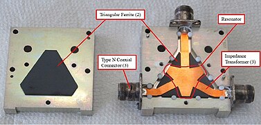 Internal construction of a stripline junction circulator having triangular ferrites and an irregular triangle-shaped resonator.
 -
 Internal construction of stripline junction circulator having disk ferrites and a disk-shaped resonator.
 -
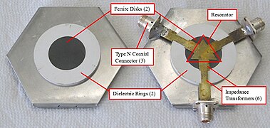 Internal construction of a stripline junction circulator having disk ferrites and a triangle-shaped resonator.


Waveguide junction circulators


A waveguide junction circulator contains a magnetized ferrite resonator, which is located at the junction of three waveguides.[8] In contrast with a stripline junction circulator, the ferrite itself is the resonator, rather than the metal central portion of a stripline center conductor. The ferrite resonator may have any shape that has three-fold Rotational symmetry, such as a cylinder or Triangular prism. The resonator is often just one ferrite, but it is sometimes composed of two or more ferrites, which may be coupled to each other, in various geometrical configurations. The geometry of the resonator is influenced by electrical and thermal performance considerations. Waveguide junction circulators function in much the same way as stripline junction circulators, and their basic theory of operation is the same.
The internal geometry of a waveguide junction circulator comprises a junction of three waveguides, the ferrite resonator, and impedance matching structures. Many of these circulators contain pedestals located in the central junction, on which the ferrite resonator is located. These pedestals effectively reduce the height of the waveguide, reducing its characteristic impedance in the resonator region to optimize electrical performance. The reduced-height waveguide sections leading from the resonator to the full-height waveguides serve as impedance transformers.
The ferrite resonator is magnetized through its height, i.e., the static magnetic bias field is perpendicular to the plane of the device and the direction of signal propagation is transverse to the direction of the static magnetic field. The static magnetic bias field is typically provided by permanent magnets that are external to the waveguide junction.
Microstrip junction circulators


The microstrip junction circulator is another widely-used form of circulator
The performance disadvantages of microstrip circulators are offset by their relative ease of integration with other planar circuitry. The electrical connections of these circulators to adjacent circuitry are typically made using wire bonds or ribbon bonds. Another advantage of microstrip circulators is their smaller size and correspondingly lower mass than stripline circulators. Despite this advantage, microstrip circulators are often the largest components in microwave modules.[10]
Self-biased junction circulators

Self-biased junction circulators are unique in that they do not utilize permanent magnets that are separate from the microwave ferrite. The elimination of external magnets significantly reduces the size and weight of the circulator compared to electrically-equivalent microstrip junction circulators for similar applications.
Monolithic ferrites that are used for self-biased circulators are M-type
Because of their thin, planar shape, self-biased circulators can be conveniently integrated with other planar circuitry. Integration of self-biased circulators with semiconductor wafers has been demonstrated at
Lumped-element circulators


Lumped-element circulators
In a lumped-element circulator, conductors are wrapped around the ferrite, forming what is typically a woven mesh. The conductor strips are insulated from each other by thin dielectric layers. In some circulators, the mesh is in the form of traces on a
This class of circulator offers a considerable size reduction compared with the junction circulators. On the other hand, lumped-element circulators generally have lower RF power handling capacity than equivalent junction devices and are more complex from a mechanical perspective. The discrete lumped-element inductors and capacitors can be less stable when exposed to vibration or mechanical shocks than the simple distributed impedance transformers in a stripline junction circulator.
Switching circulators

Switching circulators are similar to other junction circulators, and their microwave theory of operation is the same, except that their direction of circulation can be electronically controlled.[3]
Junction circulators use permanent magnets to provide the static magnetic bias for the ferrite(s). However, switching circulators typically rely on the
The magnetization polarity of the ferrite, and hence the direction of circulation of a switching circulator, is controlled using a magnetizing coil that loops through the ferrite. The coil is connected to electronic driver circuitry[8] that sends current pulses of the correct polarity through the magnetizing coil to magnetize the ferrite in the polarity to provide the desired direction of circulation.
Differential phase shift circulators


Differential phase shift circulators are mainly used in high power microwave applications. They are usually built from rectangular waveguide components. These circulators are 4-port devices having circulation in the sequence 1 - 2 - 3 - 4 - 1, with ports numbered as shown in the schematic. There are various feasible circulator architectures, the most common of which utilizes a magic tee hybrid coupler, a quadrature hybrid coupler, and two oppositely-magnetized differential phase shifters.[16]
A differential phase shifter provides non-reciprocal transmission phase shift. That is, the forward phase shift is different from the phase shift in the reverse transmission direction. It is this difference in phase shifts that enables the non-reciprocal behavior of the circulator. A differential phase shifter consists of one or more ferrite slabs, usually positioned on the broad wall(s) of the waveguide. Permanent magnets located outside the waveguide provide static magnetic bias field to the ferrite(s). The ferrite-loaded waveguide is another example of a transverse-field device as described in Circulator § Theory of operation. Different microwave propagation constants corresponding to different directions of signal propagation give rise to different phase velocities and hence, different transmission phase shifts.
Depending on which circulator port an incident signal enters, phase shift relationships in the hybrid couplers and the differential phase shifts cause signals to combine at one other port and cancel at each of the remaining two ports. Differential phase shift circulators are often used as 3-port circulators by connecting one circulator port to a reflectionless termination, or they can be used as isolators by terminating two circulator ports.

Non-ferrite circulators
Though ferrite circulators can provide good "forward" signal circulation while suppressing greatly the "reverse" circulation, their major shortcomings, especially at low frequencies, are the bulky sizes and the narrow bandwidths.
Early work on non-ferrite circulators includes active circulators using transistors that are non-reciprocal in nature.[17] In contrast to ferrite circulators which are passive devices, active circulators require power. Major issues associated with transistor-based active circulators are the power limitation and the signal-to-noise degradation,[18] which are critical when it is used as a duplexer for sustaining the strong transmit power and clean reception of the signal from the antenna.
In 1964, Mohr presented and experimentally demonstrated a circulator based on transmission lines and switches.[21] In April, 2016 a research team significantly extended this concept, presenting an integrated circuit circulator based on N-path filter concepts.[22][23] It offers the potential for full-duplex communication (transmitting and receiving at the same time with a single shared antenna over a single frequency). The device uses capacitors and a clock and is much smaller than conventional devices.[24]
Applications
Isolator
When one port of a three-port circulator is terminated in a matched load, it can be used as an isolator, since a signal can travel in only one direction between the remaining ports.[25] An isolator is used to shield equipment on its input side from the effects of conditions on its output side; for example, to prevent a microwave source being detuned by a mismatched load.
Duplexer
In radar, circulators are used as a type of duplexer, to route signals from the transmitter to the antenna and from the antenna to the receiver, without allowing signals to pass directly from transmitter to receiver. The alternative type of duplexer is a transmit-receive switch (TR switch) that alternates between connecting the antenna to the transmitter and to the receiver. The use of chirped pulses and a high dynamic range may lead to temporal overlap of the sent and received pulses, however, requiring a circulator for this function.
Reflection amplifier

A
References
- ISBN 978-1-394-15613-9.
- .
- ^ ISBN 978-1-60807-583-6.
- ISSN 0018-9480.
- ^ S2CID 111367080.
- ISBN 0-06-046367-8.
- ISBN 978-0-470-25878-1.
- ^ ISBN 0-471-98252-0.
- ISBN 0-86341-064-2.
- S2CID 148572410.
- ISSN 0018-9464.
- S2CID 46417910.
- .
- ISSN 0018-9480.
- .
- ISBN 0-471-36930-6.
- ISSN 0018-9219.
- ISSN 0018-9480.
- S2CID 13987504.
- S2CID 17421796.
- .
- ^ Nordrum, Amy (2016-04-15). "New Full Duplex Radio Chip Transmits and Receives Wireless Signals at Once". IEEE Spectrum: Technology, Engineering, and Science News. Retrieved 2016-07-22.
- PMID 27079524.
- ^ Wang, Brian (April 18, 2016). "Next Big Future: Novel miniaturized circulator opens way to doubling wireless capacity". nextbigfuture.com. Retrieved 2016-04-19.
- ^ For a description of a circulator, see Jachowski (1976)
Further reading
- Chait, H. N.; Curry, T. R. (1959), "Y-Circulator",
- US 3935549, Jachowski, Ronald E., "Ferrite Circulator", published 1976-01-27
- Linkhart, Douglas K. (2014), Microwave Circulator Design (Second ed.), Artech House, ISBN 978-1608075836
- Ohm, E. A. (1956), "A Broad-Band Microwave Circulator",
- Wenzel, C. (July 1991), "Low Frequency Circulator/Isolator Uses No Ferrite or Magnet" (PDF), RF Design, archived (PDF) from the original on 2022-10-09
External links
- Circulators and Isolators
- RF Circulators what they are, different types, how they work, etc.
+
| Authority control databases: National |
|---|