
Gangway connection


A gangway connection (or, more loosely, a corridor connection) is a flexible connector fitted to the end of a railway coach, enabling passengers to move from one coach to another without danger of falling from the train.
Origins: Coaches in British and American railways
The London and North Western Railway (LNWR) was the first British railway to provide passengers with the means to move from one coach to another while the train was in motion. In 1869 the LNWR built a pair of saloons for the use of Queen Victoria; these had six-wheel underframes (the bogie coach did not appear in Britain until 1872), and the gangway was fitted to only one end of each coach. The Queen preferred to wait until the train had stopped before using the gangway.[1][2]

In 1887,
The Great Northern Railway introduced the Gould-design[clarification needed] gangway connection to Great Britain in 1889, when E.F. Howlden was Carriage and Wagon Superintendent.[5]
In March 1892, the
The gangway connections of the early GWR corridor coaches were offset to one side.[7] Some coaches intended for use at the ends of trains had the gangway connection fitted at one end only.[8] The GWR introduced restaurant cars in 1896; gangway connections were fitted, but passengers wishing to use the restaurant car were expected to board it at the start of their journey, and remain there: the connections were still not for public use.[9]

In May 1923, the GWR introduced some new coaches on their South Wales services; some of these coaches had British Standard gangway connections[clarification needed] and screw couplers as used on many other GWR coaches; some had Pullman-type gangway connections and Laycock "buckeye" couplers; and there were some with one type at one end, and the other end having the other type.[10][11] In 1925 the GWR started to use the "suspended" form of gangway connection instead of the "scissors" pattern[clarification needed].[10][12] From 1938, GWR coaches which were expected to need coupling to LNER or SR coaches were fitted with gangway adaptors, to allow the dissimilar types to be connected.[10]
From the beginning, the London, Midland and Scottish Railway used the British Standard type of gangway connector, with its "scissors" pattern as used by the GWR. Some coaches needed for LNER or SR lines were given gangway adaptors, so that they could safely couple to coaches fitted with the Pullman-type gangway.[13]
On the formation of British Railways on 1 January 1948, operators decided to produce a new range of standard coaches, instead of perpetuating existing designs—but the new types had to be compatible with the old. Two of the pre-BR companies (the GWR and the
These gangways consisted of a flat steel plate, having a large aperture for the passageway. At the bottom it was riveted to the buffing plate, whilst the top was supported on the coach end by two telescopic spring units. On the coach end was a wooden doorframe; this was connected to the faceplate by a flexible diaphragm made from plasticised asbestos. When two coaches were coupled, a curtain was used to cover the inside surfaces of the diaphragms and faceplates. The doorframe was fitted with a lockable door, of either sliding or hinged type, depending on the interior layout of that end of the coach.[15]
Travelling post offices
Coaches built for
A disadvantage was that when a van was added to a TPO train, it might need to be turned around before it could be used. After the formation of British Railways, most new Mark 1 TPO vans were provided with centre gangways, though a batch intended to work with older vans were given offset gangways. These were altered to the standard arrangement in 1973. Until then, they had been the only BR Mark 1 gangwayed coaches not to have the Pullman gangway.[16]
Locomotives (corridor tenders)
.jpg)
A corridor tender is a locomotive tender with a passageway to one side, allowing crew changes on the fly.
The

The LNER's locomotive design team, headed by Nigel Gresley, produced a new design of tender that was slightly longer than the old, but built as high and wide as possible without compromising the loading gauge. A passageway was incorporated along the right-hand side, and at the rear end a Pullman type gangway connection was fitted, together with a buckeye coupler, both of which were compatible with LNER coaches. The gangway was of concertina pattern, and was pressed against the corresponding gangway on the leading coach by means of sprung pistons.[20]
Although a normal gangway connection was used, the passageway through the tender was only 5 feet (1.52 m) high and 18 inches (0.46 m) wide, and the floor of the passage was 2 feet (0.61 m) above the bottom of the water tank, requiring two steps at both ends. The passageway was illuminated by a single circular window in the tender rear panel, placed high up and to the right of the corridor connection.[20] Ten of these tenders were placed in service between April and September 1928, of which three were attached to new locomotives of Class A3; two were attached to existing Class A3 locomotives, and five attached to Class A1 locomotives.[21] The design was patented by Gresley in August 1928.[22]
In service, the relief crew travelled in the front coach of the train, and as the train approached the half-way point, they left their seats and made their way forward through the corridor tender to the locomotive cab. On their arrival, the previous crew then handed over the controls and went back to the seats in the train vacated by the relief crew.[23]
Another corridor tender (Number 5484) was built in 1929 for use with the new Class W1 4-6-4 no. 10000;[24] four more were built in 1935 with the first four locomotives of the new Class A4, and a final seven were built with the 1937 batch of Class A4 locomotives, making a total of 22. The original ten were reconditioned in 1936–1937 and attached to other Class A4 locomotives. In May 1948, the 1929-built corridor tender was transferred to a locomotive of Class A4, after which all 22 remained with this class until withdrawal.[23][25][26]
Open gangways in urban transit
-
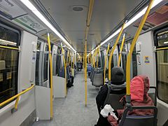 Interior view of theBombardier Innovia Metro300 (Mark III)
 -
 Interior view of the MPM-10 Azur train
 -
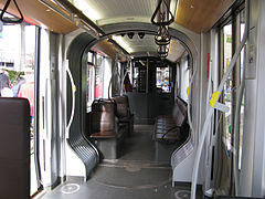 Open gangway on a Bombardier Flexity Outlook tram
 -
 Open gangway on an R211T
 -
 Interior of aSydney Metro Alstom Metropolis TS set


In urban transit, open gangways are most commonly used in
The NYC Subway was the first transit authority in the world to have a subway / metro system with open gangways, with the
In North America, the
The Metropolitan Transportation Authority (MTA) has ordered 20 experimental open gangway cars as part of the NYC Subway's R211 order. These began running on the C line on February 1, 2024.[30] The order initially consists of 545 cars, of which 20 are the open gangway prototype sets. There are two designs, the first ten cars utilizing interior panels in the gangway connection, and the other ten cars using interior bellows in the gangway connection. The latter design also contains a wider walkway and handles between cars. Depending on the success of the prototype sets, the R211 order includes an option to purchase up to 437 additional open gangway cars.[31]
While not technically an open gangway because of the use of doors, BART permits passengers to walk between cars via a more traditional gangway connection. This has been a feature since its opening in 1972.
The open gangway design has been incorporated into
(Moskva).Some trains, like U-Bahn BVG Class HK, S-Bahn DBAG Class 481, 81-740 Rusich etc. use open gangways only between car pairs or 3-car sets; recent versions of these trains, Class IK, Class 483 and 81-760 Oka/81-765 Moskva, employ full walkthrough gangway along entire train.
Multiple units and TurboTrain (walk-through heads)
-
 JR 285 series
 -
 Dutch ICM
 -
 Danish DSB IC3
 -
 JR E351 series
 -

-
 UAC TurboTrain power car


.jpg)

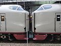
A walk-through head is a type of gangway connection that is installed in a train set that is intended to enable the passage from one train to the next when they are interconnected.
With most matched multiple-units, it is possible, as with locomotive-towed carriages, to walk from one unit to another, but a passage between adjacent cabbed ends of coupled trains is less common.
See also
- Anticlimber
- Buffers and chain coupler
- Janney coupler
- Railway coupling
- SA3 coupler
- Tightlock coupler
- Vestibule
- Vestibuled train
Notes
- ^ Jenkinson 1978, p. 117.
- ^ Jenkinson 1988, p. 10.
- ^ Chant 2002, p. 348.
- ^ Solomon 2001, p. 101.
- ^ Harris 1995, p. 9.
- ^ Harris 1985, p. 38.
- ^ Harris 1985, p. 23.
- ^ Harris 1985, p. 40.
- ^ Harris 1985, pp. 48, 51.
- ^ a b c Harris 1985, p. 24.
- ^ Harris 1985, p. 75.
- ^ Harris 1985, p. 77.
- ^ Essery & Jenkinson 1991, p. 7.
- ^ Parkin 1991, p. 7,8.
- ^ Parkin 1991, p. 18,26.
- ^ a b Parkin 1991, p. 175.
- ^ Boddy, Neve & Yeadon 1973, pp. 75–76.
- ^ Nock 1945, p. 46.
- ^ Boddy, Neve & Yeadon 1973, p. 68.
- ^ a b Boddy, Neve & Yeadon 1973, pp. 68, 112.
- ^ Boddy, Neve & Yeadon 1973, pp. 68–69.
- ^ Hughes 2001, p. 95.
- ^ a b Boddy et al. 1963, p. 64.
- ^ Boddy et al. 1984, p. 149.
- ^ Boddy, Neve & Yeadon 1973, pp. 112–3.
- ^ Boddy et al. 1984, p. 156.
- ^ Danielle Furfaro (August 16, 2016). "Here's a glimpse at the future on NYC's subways". New York Post. Retrieved August 16, 2016.
- ^ "TTC unveils new subway cars". CP24. 2010-10-14. Retrieved 2012-12-05.
- ^ STM societyinmotion.org http://www.mouvementcollectif.org/SWF/?en/#/metro-cars
- ^ Siff • •, Andrew (February 1, 2024). "MTA debuts new 'open gangway' subway cars. Here's why you'll like them". NBC New York. Retrieved February 1, 2024.
- ^ "Governor Cuomo Unveils Design of Reimagined MTA Subway Cars and Details Ambitious Plan to Enhance Subway Stations". 2016-07-18. Archived from the original on 2016-08-05. Retrieved 2016-07-19.
References
- Boddy, M.G.; Fry, E.V.; Hennigan, W.; Proud, P.; Yeadon, W.B. (July 1963). Fry, E.V. (ed.). Part 1: Preliminary Survey. Locomotives of the L.N.E.R. Potters Bar: RCTS.
- Boddy, M.G.; Neve, E.; Yeadon, W.B. (April 1973). Fry, E.V. (ed.). Part 2A: Tender Engines - Classes A1 to A10. Locomotives of the L.N.E.R. Kenilworth: ISBN 0-901115-25-8.
- Boddy, M. G.; Brown, W. A.; Hennigan, W.; ISBN 0-901115-55-X.
- Chant, Christopher (2002). The History of North American Rail. Edison, NJ: Chartwell Books. ISBN 0-7858-1455-8.
- ISBN 0-86093-450-0. T450.
- Harris, Michael (1985) [1966]. Great Western Coaches from 1890 (3rd ed.). Newton Abbot: ISBN 0-7153-8050-8.
- Harris, Michael (1995). Great Northern Railway and East Coast Joint Stock Carriages from 1905. Headington: Oakwood Press. ISBN 0-85361-477-6. X56.
- Hughes, Geoffrey (2001). Sir Nigel Gresley: The Engineer and his Family. The Oakwood Library of Railway History. Usk: Oakwood Press. ISBN 0-85361-579-9. OL118.
- ISBN 0-902888-90-0.
- Jenkinson, David (1988). British Railway Carriages of the 20th Century - Volume 1: The end of an era, 1901-22. London: Guild Publishing. CN 8130.
- Nock, O.S. (1945). The Locomotives of Sir Nigel Gresley. London: Longmans, Green & Co. 16925.
- Parkin, Keith (1991). British Railways Mark 1 Coaches. Penryn: Pendragon. ISBN 0-906899-49-4.
- Solomon, Brian (2001). The Heritage of North American Steam Railroads. London: Amber Books. ISBN 1-897884-75-3.