
Hydraulic analogy

Electronic-hydraulic analogies are the representation of electronic circuits by hydraulic circuits. Since
The electronic–hydraulic analogy (derisively referred to as the drain-pipe theory by Oliver Lodge) [1] is the most widely used analogy for "electron fluid" in a metal conductor. As with all analogies, it demands an intuitive and competent understanding of the baseline paradigms (electronics and hydraulics), and in the case of the hydraulic analogy for electronics, students often have an inadequate knowledge of hydraulics.[2]
Paradigms
There is no unique paradigm for establishing this analogy. Different paradigms have different strengths and weaknesses, depending on how and in what ways the intuitive understanding of the source of the analogy matches with phenomena in electronics.[2] Two paradigms can be used to introduce the concept to students using pressure induced by gravity or by pumps.
In the version with pressure induced by gravity, large tanks of water are held up high, or are filled to differing water levels, and the potential energy of the water
A second paradigm is a completely enclosed version with pumps providing pressure only and no gravity. This is reminiscent of a circuit diagram with a voltage source shown and the wires actually completing a circuit. This paradigm is further discussed below.
Other paradigms highlight the similarities between equations governing the flow of fluid and the flow of charge. Flow and pressure variables can be calculated in both steady and transient fluid flow situations with the use of the
A slightly different paradigm is used in acoustics, where acoustic impedance is defined as a relationship between acoustic pressure and acoustic particle velocity. In this paradigm, a large cavity with a hole is analogous to a capacitor that stores compressional energy when the time-dependent pressure deviates from atmospheric pressure. A hole (or long tube) is analogous to an inductor that stores kinetic energy associated with the flow of air.[6]
Hydraulic analogy with horizontal water flow
Voltage, current, and charge
In general,
A unit of electric charge is analogous to a unit volume of water.
Basic circuit elements
-
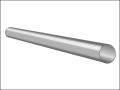 Conducting wire: a simple hose.
 -
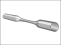 Resistor: a constricted pipe.
 -
 Node inpipe teefilled with flowing water.
.svg)
.svg)

A relatively wide hose completely filled with water is equivalent to a conducting wire. A rigidly mounted pipe is equivalent to a trace on a circuit board. When comparing to a trace or wire, the hose or pipe should be thought of as having semi-permanent caps on the ends. Connecting one end of a wire to a circuit is equivalent to un-capping one end of the hose and attaching it to another. With few exceptions (such as a high-voltage power source), a wire with only one end attached to a circuit will do nothing; the hose remains capped on the free end, and thus adds nothing to the circuit.
A resistor is equivalent to a constriction in the bore of a pipe which requires more pressure to pass the same amount of water. All pipes have some resistance to flow, just as all wires and traces have some resistance to current.
A node (or junction) in
-
 Capacitor: a flexible diaphragm sealed inside a pipe.
 -
 Inductor: a rotary vane pump with a heavy rotor, or a turbine placed in the current.
 -


A capacitor is equivalent to a tank with one connection at each end and a rubber sheet dividing the tank in two lengthwise[7] (a hydraulic accumulator). When water is forced into one pipe, equal water is simultaneously forced out of the other pipe, yet no water can penetrate the rubber diaphragm. Energy is stored by the stretching of the rubber. As more current flows "through" the capacitor, the back-pressure (voltage) becomes greater, thus current "leads" voltage in a capacitor. As the back-pressure from the stretched rubber approaches the applied pressure, the current becomes less and less. Thus capacitors "filter out" constant pressure differences and slowly varying, low-frequency pressure differences, while allowing rapid changes in pressure to pass through.
An
An ideal
Other circuit elements
-
 A simple one-way ball-type check valve, in its "open" state acts as a diode in its conducting state.
 -
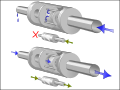
 A pressure-actuated valve combined with a one-way check valve acts as a (field-effect) transistor.
 -
 Like a one-way check valve, a diode blocks current that flows the wrong way. Current that flows the right way goes through almost unchanged.
 -
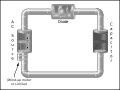 A simple A/C circuit consisting of an oscillating pump, a "diode" valve, and a "capacitor" tank. Any kind of motor could be used here to drive the pump, as long as it oscillates.
.svg)
.svg)
.svg)

A diode is equivalent to a one-way check valve with a slightly leaky valve seat. As with a diode, a small pressure difference is needed before the valve opens. And like a diode, too much reverse bias can damage or destroy the valve assembly.
A
CMOS is a combination of two MOSFET transistors. As the input pressure changes, the pistons allow the output to connect to either zero or positive pressure.
A memristor is a needle valve operated by a flow meter. As water flows through in the forward direction, the needle valve restricts flow more; as water flows the other direction, the needle valve opens further, providing less resistance.
Practical application
On the basis of this analogy Johan van Veen developed around 1937[8] a method to compute tidal currents with an electric analogue. After the North Sea flood of 1953 in The Netherlands he elaborated this idea, which eventually lead to the analog computer ‘’Deltar’’, which was used to make the hydraulic computations for the closures in the framework of the Delta Works.
Principal equivalents
EM wave speed (
Charge flow speed (drift velocity) is equivalent to the particle speed of water. The moving charges themselves move rather slowly.
DC is equivalent to a constant flow of water in a circuit of pipes.
Low frequency AC is equivalent to water oscillating back and forth in a pipe
Higher-frequency AC and transmission lines is somewhat equivalent to sound being transmitted through the water pipes, though this does not properly mirror the cyclical reversal of alternating electric current. As described, the fluid flow conveys pressure fluctuations, but fluids do not reverse at high rates in hydraulic systems, which the above "low frequency" entry does accurately describe. A better concept (if sound waves are to be the phenomenon) is that of direct current with high-frequency "ripple" superimposed.
Inductive spark used in induction coils is similar to water hammer, caused by the inertia of water.
Equation examples
| type | hydraulic
|
electric
|
thermal | mechanical |
|---|---|---|---|---|
| quantity | volume [m3] | charge [C] | heat [J] | momentum [Ns] |
| quantity flux | Volumetric flow rate [m3/s] | current [A=C/s]
|
heat transfer rate [J/s]
|
velocity [m/s=J/Ns] |
| flux density | velocity [m/s] | current density [C/(m2·s) = A/m2] | heat flux [W/m2] | stress [N/m2 = Pa] |
| potential | pressure [Pa=J/m3=N/m2] | potential [V=J/C=W/A] | temperature [K] | force [N] |
| linear model | Poiseuille's law
|
Ohm's law | Fourier's law
|
dashpot |


If the differential equations are equivalent in form, the dynamics of the systems they describe will be related. The example hydraulic equations approximately describe the relationship between a constant, laminar flow in a cylindrical pipe and the difference in pressure at each end, as long as the flow is not analyzed near the ends of the pipe. The example electric equations approximately describe the relationship between a current in a straight wire and the difference in electric potential (voltage). In these two cases, the states of both systems are well-approximated by the differential equations above, and so the states are related. The assumptions that make these differential equations good approximates are needed for this relationship. Any deviations from the assumptions (e.g. pipe or wire is not straight, flow or current is changing over time, other factors are influencing potential) can make the relationship fail to hold. The differential equations for hydraulics and electronics above are special cases of the Navier–Stokes equations and Maxwell's equations, respectively, and the two are not equivalent in form.
Limits to the analogy
This section needs additional citations for verification. (December 2022) |
If taken too far, the water analogy can create misconceptions.
Charge: Unlike water, movable charge carriers can be positive or negative, and conductors can exhibit an overall positive or negative net charge. The mobile carriers in electric currents are usually electrons, but sometimes they are charged positively, such as the positive ions in an
Leaking pipes: The
Fluid velocity and resistance of metals: As with water hoses, the carrier drift velocity in conductors is directly proportional to current. However, water only experiences drag via the pipes' inner surface, while charges are slowed at all points within a metal, as with water forced through a filter. Also, typical velocity of charge carriers within a conductor is less than centimeters per minute, and the "electrical friction" is extremely high. If charges ever flowed as fast as water can flow in pipes, the electric current would be immense, and the conductors would become incandescently hot and perhaps vaporize. To model the resistance and the charge-velocity of metals, perhaps a pipe packed with sponge, or a narrow straw filled with syrup, would be a better analogy than a large-diameter water pipe.
In order for the model to be useful, the reader or student must have a substantial understanding of the model (hydraulic) system's principles. It also requires that the principles can be transferred to the target (electrical) system. Hydraulic systems are deceptively simple: the phenomenon of pump cavitation is a known, complex problem that few people outside of the fluid power or irrigation industries would understand. For those who do, the hydraulic analogy is amusing, as no "cavitation" equivalent exists in electrical engineering. The hydraulic analogy can give a mistaken sense of understanding that will be exposed once a detailed description of electrical circuit theory is required.
One must also consider the difficulties in trying to make an analogy match reality completely. The above "electrical friction" example, where the hydraulic analog is a pipe filled with sponge material, illustrates the problem: the model must be increased in complexity beyond any realistic scenario.
See also
- Bond graph
- Fluidics
- Hydraulic circuit
- Hydraulic conductivity
- Mechanical–electrical analogies
Notes
- ^ Paul J. Nahin, Oliver Heaviside: The Life, Work, and Times of an Electrical Genius of the Victorian Age, JHU Press, 2002
ISBN 0801869099page 59
- ^ S2CID 143043431. Retrieved 2022-12-09.
- ISBN 0-8247-9956-9.
- ^ A. Esposito, "A Simplified Method for Analyzing Circuits by Analogy". Machine Design, October 1969, pp. 173-177.
- ISBN 1139489836.
- ^ Schelleng, John C. "The violin as a circuit". The Journal of the Acoustical Society of America 35.3 (2005): 326-338. maestronet.com
- ^ "ELECTRICITY MISCONCEPTIONS: Capacitor". amasci.com.
- ^ Van Veen, Johan (1937). The analogy between tides and electrical currents] (PDF). Rijkswaterstaat BER037.