
Metal lathe

In machining, a metal lathe or metalworking lathe is a large class of lathes designed for precisely machining relatively hard materials. They were originally designed to machine metals; however, with the advent of plastics and other materials, and with their inherent versatility, they are used in a wide range of applications, and a broad range of materials. In machining jargon, where the larger context is already understood, they are usually simply called lathes, or else referred to by more-specific subtype names (toolroom lathe, turret lathe, etc.). These rigid machine tools remove material from a rotating workpiece via the (typically linear) movements of various cutting tools, such as tool bits and drill bits.
Construction
The design of lathes can vary greatly depending on the intended application; however, basic features are common to most types. These machines consist of (at the least) a headstock, bed, carriage, and tailstock. Better machines are solidly constructed with broad bearing surfaces (slide-ways) for stability, and manufactured with great precision. This helps ensure the components manufactured on the machines can meet the required tolerances and repeatability.
Headstock

The headstock (H1) houses the main spindle (H4), speed change mechanism (H2, H3), and change gears (H10). The headstock is required to be made as robust as possible due to the cutting forces involved, which can distort a lightly built housing, and induce harmonic vibrations that will transfer through to the workpiece, reducing the quality of the finished workpiece.
The main spindle is generally hollow to allow long bars to extend through to the work area. This reduces preparation and waste of material. The spindle runs in precision bearings and is fitted with some means of attaching workholding devices such as
Beds
The bed is a robust base that connects to the headstock and permits the carriage and tailstock to be moved parallel with the axis of the spindle. This is facilitated by hardened and ground bedways which restrain the carriage and tailstock in a set track. The carriage travels by means of a rack and pinion system. The leadscrew of accurate pitch, drives the carriage holding the cutting tool via a gearbox driven from the headstock.
Types of beds include inverted "V" beds, flat beds, and combination "V" and flat beds. "V" and combination beds are used for precision and light duty work, while flat beds are used for heavy duty work.[citation needed]
When a lathe is installed, the first step is to level it, which refers to making sure the bed is not twisted or bowed. There is no need to make the machine exactly horizontal, but it must be entirely untwisted to achieve accurate cutting geometry. A precision level is a useful tool for identifying and removing any twist. It is advisable also to use such a level along the bed to detect bending, in the case of a lathe with more than four mounting points. In both instances the level is used as a comparator rather than an absolute reference.
Feed and lead screws
The feedscrew (H8) is a long
Some lathes have only one leadscrew that serves all carriage-moving purposes. For screw cutting, a half nut is engaged to be driven by the leadscrew's thread; and for general power feed, a key engages with a keyway cut into the leadscrew to drive a pinion along a rack that is mounted along the lathe bed.
The leadscrew will be manufactured to either
The precise ratio required to convert a lathe with an Imperial (inch) leadscrew to metric (millimeter) threading is 100 / 127 = 0.7874... . The best approximation with the fewest total teeth is very often 37 / 47 = 0.7872... . This transposition gives a constant -0.020 percent error over all customary and model-maker's metric pitches (0.25, 0.30, 0.35, 0.40, 0.45, 0.50, 0.60, 0.70, 0.75, 0.80, 1.00, 1.25, 1.50, 1.75, 2.00, 2.50, 3.00, 3.50, 4.00, 4.50, 5.00, 5.50 and 6.00 mm).
Carriage

- Toolpost
- Compound/top-slide
- Cross-slide
- Saddle
- Apron
In its simplest form the carriage holds the tool bit and moves it longitudinally (turning) or perpendicularly (facing) under the control of the operator. The operator moves the carriage manually via the handwheel (5a) or automatically by engaging the feed shaft with the carriage feed mechanism (5c). This provides some relief for the operator as the movement of the carriage becomes power assisted. The handwheels (2a, 3b, 5a) on the carriage and its related slides are usually calibrated, both for ease of use and to assist in making reproducible cuts. The carriage typically comprises a top casting, known as the saddle (4), and a side casting, known as the apron (5).
Cross-slide
The cross-slide (3) rides on the carriage and has a feedscrew which travels at right angles to the main spindle axis. This permits facing operations to be performed, and the depth of cut to be adjusted. This feedscrew can be engaged, through a gear train, to the feed shaft (mentioned previously) to provide automated 'power feed' movement to the cross-slide. On most lathes, only one direction can be engaged at a time as an interlock mechanism will shut out the second gear train.
Cross-slide handwheels are usually marked in terms of the part's diameter, so one graduation representing .001 inches of diameter corresponds to .0005 inches of cross-slide motion.
Compound rest
The compound rest (or top slide) (2) is usually where the tool post is mounted. It provides a smaller amount of movement (less than the cross-slide) along its axis via another feedscrew. The compound rest axis can be adjusted independently of the carriage or cross-slide. It is used for turning tapers, to control depth of cut when screwcutting or precision facing, or to obtain finer feeds (under manual control) than the feed shaft permits. Usually, the compound rest has a protractor marked in its base (2b), enabling the operator to adjust its axis to precise angles.
The slide rest (as the earliest forms of carriage were known) can be traced to the fifteenth century. In 1718 the tool-supporting slide rest with a set of gears was introduced by a Russian inventor Andrey Nartov and had limited usage in the Russian industry.[1]
The first fully documented, all-metal slide rest lathe was invented by Jacques de Vaucanson around 1751. It was described in the Encyclopédie a long time before Maudslay invented and perfected his version. It is likely that Maudslay was not aware of Vaucanson's work, since his first versions of the slide rest had many errors that were not present in the Vaucanson lathe.
In the eighteenth century the slide rest was also used on French ornamental turning lathes.
The suite of gun boring mills at the Royal Arsenal, Woolwich, in the 1780s by the Verbruggan family also had slide rests. The story has long circulated that Henry Maudslay invented it, but he did not (and never claimed so). The legend that Maudslay invented the slide rest originated with James Nasmyth, who wrote ambiguously about it in his Remarks on the Introduction of the Slide Principle, 1841;[2] later writers misunderstood, and propagated the error. However, Maudslay did help to disseminate the idea widely. It is highly probable that he saw it when he was working at the Arsenal as a boy. In 1794, whilst he was working for Joseph Bramah, he made one, and when he had his own workshop used it extensively in the lathes he made and sold there. Coupled with the network of engineers he trained, this ensured the slide rest became widely known and copied by other lathe makers, and so diffused throughout British engineering workshops. A practical and versatile screw-cutting lathe incorporating the trio of leadscrew, change gears, and slide rest was Maudslay's most important achievement.
Toolpost
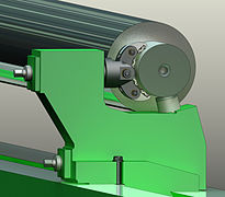
The tool bit is mounted in the toolpost (1) which may be of the American lantern style, traditional four-sided square style, or a quick-change style such as the multi-fix arrangement pictured. The advantage of a quick change set-up is to allow an unlimited number of tools to be used (up to the number of holders available) rather than being limited to one tool with the lantern style, or to four tools with the four-sided type. Interchangeable tool holders allow all tools to be preset to a center height that does not change, even if the holder is removed from the machine.
Tailstock

The
The image shows a reduction gear box (T2) between the handwheel and spindle, where large drills may necessitate the extra leverage. The tool bit is normally made of HSS, cobalt steel or carbide.
Steady, follower and other rests
Long workpieces often need to be supported in the middle, as cutting tools can push (bend) the work piece away from where the centers can support them, because cutting metal produces tremendous forces that tend to vibrate or even bend the workpiece. This extra support can be provided by a steady rest (also called a steady, a fixed steady, a center rest, or sometimes, confusingly, a center). It stands stationary from a rigid mounting on the bed, and it supports the workpiece at the rest's center, typically with three contact points 120° apart. A follower rest (also called a follower or a travelling steady) is similar, but it is mounted to the carriage rather than the bed, which means that as the tool bit moves, the follower rest "follows along" (because they are both rigidly connected to the same moving carriage).[3][4]
Follower rests can provide support that directly counteracts the springing force of the tool bit, right at the region of the workpiece being cut at any moment. In this respect they are analogous to a box tool. Any rest transfers some workpiece geometry errors from base (bearing surface) to processing surface. It depends on the rest design. For minimum transfer rate correcting rests are used. Rest rollers typically cause some additional geometry errors on the processing surface.
-
 A steady rest
 -
 A follower rest
 -
 Correcting rest for precision grinding or turning
 -
Correcting rest work video


Types of metal lathes
There are many variants of lathes within the metalworking field. Some variations are not all that obvious, and others are more a niche area. For example, a centering lathe is a dual head machine where the work remains fixed and the heads move towards the workpiece and machine a center drill hole into each end. The resulting workpiece may then be used "between centers" in another operation. The usage of the term metal lathe may also be considered somewhat outdated these days. Plastics and other composite materials are in wide use and, with appropriate modifications, the same principles and techniques may be applied to their machining as that used for metal.
Center lathe / engine lathe / bench lathe

The terms center lathe, engine lathe, and bench lathe all refer to a basic type of lathe that may be considered the archetypical class of metalworking lathe most often used by the general machinist or machining hobbyist. The name bench lathe implies a version of this class small enough to be mounted on a workbench (but still full-featured, and larger than mini-lathes or micro-lathes). The construction of a center lathe is detailed above, but depending on the year of manufacture, size, price range or desired features, even these lathes can vary widely between models.
Engine lathe is the name applied to a traditional late-19th-century or 20th-century lathe with automatic feed to the cutting tool, as opposed to early lathes which were used with hand-held tools, or lathes with manual feed only. The usage of "engine" here is in the mechanical-device sense, not the prime-mover sense, as in the steam engines which were the standard industrial power source for many years. The works would have one large steam engine which would provide power to all the machines via a line shaft system of belts. Therefore, early engine lathes were generally 'cone heads', in that the spindle usually had attached to it a multi-step pulley called a cone pulley designed to accept a flat belt. Different spindle speeds could be obtained by moving the flat belt to different steps on the cone pulley. Cone-head lathes usually had a countershaft (layshaft) on the back side of the cone which could be engaged to provide a lower set of speeds than was obtainable by direct belt drive. These gears were called back gears. Larger lathes sometimes had two-speed back gears which could be shifted to provide a still lower set of speeds.
When electric motors started to become common in the early 20th century, many cone-head lathes were converted to electric power. At the same time the state of the art in
The availability of inexpensive electronics has again changed the way speed control may be applied by allowing continuously variable motor speed from the maximum down to almost zero RPM. This had been tried in the late 19th century but was not found satisfactory at the time. Subsequent improvements in electric circuitry have made it viable again.
Toolroom lathe
A toolroom lathe is a lathe optimized for
Turret lathe and capstan lathe
There is a tremendous variety of turret lathe and capstan lathe designs, reflecting the variety of work that they do.
Gang-tool lathe
A gang-tool lathe is one that has a row of tools set up on its cross-slide, which is long and flat and is similar to a
Multispindle lathe
Multispindle lathes have more than one spindle and automated control (whether via
CNC lathe / CNC turning center


The machine is controlled electronically via a computer menu style interface, the program may be modified and displayed at the machine, along with a simulated view of the process. The setter/operator needs a high level of skill to perform the process. However, the knowledge base is broader compared to the older production machines where intimate knowledge of each machine was considered essential. These machines are often set and operated by the same person, where the operator will supervise a small number of machines (cell).
The design of a CNC lathe varies with different manufacturers, but they all have some common elements. The turret holds the tool holders and indexes them as needed, the spindle holds the workpiece and there are slides that let the turret move in multiple axes simultaneously. The machines are often totally enclosed, due in large part to occupational health and safety (OH&S) issues.
With rapid growth in this industry, different CNC lathe manufacturers use different user interfaces which sometimes makes it difficult for operators as they have to be acquainted with them. With the advent of cheap computers, free operating systems such as Linux, and open source CNC software, the entry price of CNC machines has plummeted.[citation needed]
Swiss-style lathe / Swiss turning center

A Swiss-style lathe is a specific design of lathe providing extreme accuracy (sometimes holding tolerances as small as a few tenths of a thousandth of an inch—a few
Most CNC Swiss-style lathes today use one or two main spindles plus one or two back spindles (secondary spindles). The main spindle is used with the guide bushing for the main machining operations. The secondary spindle is located behind the part, aligned on the Z axis. In simple operation it picks up the part as it is cut off, and accepts it for second operations, then ejects it into a bin, eliminating the need to have an operator manually change each part, as is often the case with standard CNC turning centers. This makes them very efficient, as these machines are capable of fast cycle times, producing simple parts in one cycle (i.e., no need for a second machine to finish the part with second operations), in as little as 10–15 seconds. This makes them ideal for large production runs of small-diameter parts.
Swiss-style Lathes and Live Tooling
As many Swiss lathes incorporate a secondary spindle, or 'sub-spindle', they also incorporate 'live tooling'. Live tools are rotary cutting tools that are powered by a small motor independently of the spindle motor. Live tools increase the intricacy of components that can be manufactured by the Swiss lathe. For instance, automatically producing a part with a hole drilled perpendicular to the main axis (the axis of rotation of the spindles) is very economical with live tooling, and similarly uneconomical if done as a secondary operation after machining by the Swiss lathe is complete. A 'secondary operation' is a machining operation requiring a partially completed part to be secured in a second machine to complete the manufacturing process. Generally, advanced CAD/CAM software uses live tools in addition to the main spindles so that most parts that can be drawn by a CAD system can actually be manufactured by the machines that the CAD/CAM software support.
Combination lathe / 3-in-1 machine
A combination lathe, often known as a 3-in-1 machine, introduces drilling or milling operations into the design of the lathe. These machines have a milling column rising up above the lathe bed, and they utilize the carriage and topslide as the X and Y axes for the milling column. The 3-in-1 name comes from the idea of having a lathe, milling machine, and
Mini-lathe and micro-lathe
Mini-lathes and micro-lathes are miniature versions of a general-purpose center lathe (engine lathe). They typically only handle work of 3 to 7 in (76 to 178 mm) diameter (in other words, 1.5 to 3.5 in (38 to 89 mm) radius). They are small and affordable lathes for the home workshop or MRO shop. The same advantages and disadvantages apply to these machines as explained earlier regarding 3-in-1 machines.
As found elsewhere in English-language orthography, there is variation in the styling of the prefixes in these machines' names. They are alternately styled as mini lathe, minilathe, and mini-lathe and as micro lathe, microlathe, and micro-lathe.
Brake lathe
A lathe specialized for the task of resurfacing brake drums and discs in automotive or truck garages.
Wheel lathe
Wheel lathes are machines used to manufacture and resurface the wheels of railway rolling stock. When wheels become worn or compromised from excessive use, this tool can be used to re-cut and recondition the wheel. There are a number of different wheel lathes available including underfloor variations for resurfacing wheels that are still attached to the rail car, portable types that are easily transported for emergency wheel repairs, and CNC versions which utilize computer-based operating systems to complete the wheel repair.[6]
Pit lathe
A lathe for large diameter, though short work, built over a recess in the floor to admit the lower part of the workpiece thus allowing the toolrest to stand at the turner's waist height. An example is on display at the London Science Museum, Kensington.
Vertical lathe
For even larger diameter and heavier work, such as pressure vessels or marine engines, the lathe is rotated so it takes the form of a turntable on which parts are placed. This orientation is less convenient for the operator, but makes it easier to support large parts. In the largest, the turntable is installed flush with the floor, with the headstock recessed below, to facilitate loading and unloading workpieces.
Because operator access is less of an issue for them, CNC vertical turning machines are more popular than manual vertical lathes.
Oil country lathe
Specialised lathes for machining long workpieces such as segments of drill strings. Oil country lathes are equipped with large-bore hollow spindles, a second chuck on the opposite side of the headstock, and frequently outboard steadies for supporting long workpieces.
Feed mechanisms
Various feed mechanisms exist to feed material into a lathe at a defined rate. The aim of these mechanisms is to automate part of the production process with the end goal of improving productivity.
Bar feeder
A bar feeder feeds a single piece of bar stock into the cutting machine. As each part is machined, the cutting tool creates a final cut to separate the part from the bar stock, and the feeder continues to feed the bar for the next part, allowing for continual operation of the machine. There are two types of bar feeds used in lathe machining: Hydrodynamic bar feeds, which rest the bar stock in a series of channels whilst clamping down on the top and bottom of the bar, and hydrostatic bar feeds, which hold the bar stock in a feed tube using pressurized oil.[7]
Bar loader
A bar loader is a variation on the bar feeder concept in that multiple pieces of bar stock may be fed into a hopper, and the loader feeds each piece as necessary.
References
- ^ Nartov's biography (in Russian)
- ^ Naysmith, James (1841). "Remarks on the introduction of the slide principle in tools and machines employed in the production of machinery". In Buchnan, Robertson; Tredgold, Thomas; Rennie, George (eds.). Practical Essays on Mill Work and other Machinery (3rd ed.). London: John Weale. p. 401.
I allude to the late Henry Maudslay, engineer, of London, whose useful life was enthusiastically devoted to the grand object of improving our means of producing perfect workmanship and machinery; to him we are certainly indebted for the slide rest, and consequently, to say the least, we are indirectly so for the vast benefits which have resulted from the introduction of so powerful an agent in perfecting our machinery and mechanism generally.
- ^ Burghardt 1919, p. 118.
- ^ Arthur R. Meyers, Thomas J. Slattery. Basic Machining Reference Handbook. Second Edition. - Industrial Press Inc., 2001, p. 58[1]
- ISBN 978-0-9897906-0-4.
- ^ "What Is a Wheel Lathe? (with picture)". wiseGEEK. Retrieved 2016-01-11.
- ^ "Bar Feeds : Production Machining". www.productionmachining.com. Retrieved 2016-01-11.
Bibliography
- Burghardt, Henry D. (1919), Machine Tool Operation, vol. 1 (1st ed.), New York, NY, USA: McGraw-Hill, LCCN 20026190.
External links
- Machine Tool Archive
- Medieval and Renaissance lathes
- The development of the lathe
- Spring pole lathe
- On ye art and mystery of Turning Archived 2009-12-25 at the Wayback Machine
- Video showing the gang tool concept
- Video showing a CNC screw machine cycle
- CNC Turning?
- CNC Lathe Tool Turret
- Social CNC Machine Tool Network