
User:Elcap/Bad caps
This article may require copy editing for grammar, style, cohesion, tone, or spelling. |
Capacitor plague

The capacitor plague was a problem with the higher than expected premature failure rate of aluminum electrolytic capacitors with non-solid or liquid electrolyte between 1999 and 2007, especially brands from some Taiwanese manufacturers.[1][2] The capacitors failed premature due to an insufficient composed electrolyte which has led to a water based corrosion effect accompanied by gas generation, causing the capacitors case to bulge, venting the electrolyte and even rupture.
High failure rates in many well-known electronic equipment brands occurred particularly in motherboards, video cards, and power supplies of personal computers, causing failures of the devices.
Excitement
First announcements
Faulty capacitors have been discovered in electronic equipment at various times, but the first flawed capacitors linked to Taiwanese raw material problems were reported by an industry publication in September 2002[1] Short time later two mainstream electronics journals began to report widespread premature defective capacitors from Taiwanese manufacturers in motherboards.[3][4]
These publications achieve engineers and other technically interested specialists without great response in the public. However, that changes after Carey Holzman published his experiences about “leaking capacitors” in the Overclockers performance community.[5]
Computer symptoms
The broad public was particularly aware to the incident occurring to the e-cap failures, because failures of PC's or desktop computers heaped beginning in the years 2001 2002. In this failed computer systems, "bad caps" are often found in power supply units, but also on
Some common behavioral symptoms of "bad caps" seen in computer systems are:
- Intermittent failure to turn on, requiring user to press reset or try turning the computer on repeatedly
- Instabilities (hangs, occurrences of the "Blue Screen of Death", kernel panics, etc.), especially when symptoms get progressively more frequent over time
- Memory errors, especially ones that get more frequent with time
- Spontaneous restarts or resets
- In on-board or add-on video cards, unstable image in some video modes
- Failure to complete the Power-On Self Test("POST"), or spontaneous rebooting before it is completed
- Failure to even start the POST; fans spin but the system appears dead
Unlike physical signs which are conclusive evidence that the capacitors are failing, many of the operational signs may be caused by other factors, such as a failing
If any of the listed symptoms are experienced, removing the system unit's case and inspecting the capacitors, especially those around the CPU, may immediately identify bad capacitors as the cause.
Visual capacitor symptoms

In case of failure of a PC or another electronic device, when opening the device, the failed capacitors were easily recognizable with clear visible fault symptoms. Visual inspection was the most common method of identifying failed capacitors.[6] The visible fault symptoms are:
- Bulging of the vent on top of the capacitor. (The "vent" is shaped by an impression stamped into the top of the can, forming the seams of the vent. It is designed so that if the capacitor becomes pressurized it will split at the vent's seams, relieving the pressure rather than exploding.)
- Broken or cracked vent on top of the capacitor, often accompanied with visible crusty rust-like brown or red deposits which is dried out electrolyte.
- Capacitor casing sitting crooked on the circuit board, as the bottom rubber plug is pushed out.
-
 Failed Chhsi capacitor with crusty electrolyte buildup on the top
 -
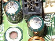
 Failed capacitors next to CPU motherboard socket
 -
 Failed Tayeh capacitors which have vented subtly through their aluminum tops
 -
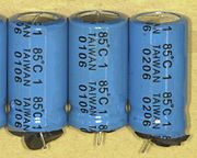 Failed electrolytic capacitors with swollen can tops and expelled rubber seals, dates of manufacture "0106" and "0206" (June 2001 and June 2002)
 -
 Failed capacitor has exploded and exposed internal elements, and another has partially blown off its casing
 -
 Failed Choyo capacitors (black color) which have leaked brownish electrolyte onto the motherboard


Sometimes electrolyte leaked onto the motherboard from the base of the capacitor, visible as dark brown or black surface deposits on the PCB. In seldom cases the leaking electrolyte has led to a small brand on the PCB. (The leaked electrolyte can be confused with thick elastic glue sometimes used to secure the capacitors to the board if vibration or shock occurs during transportation. A dark brown or black crust up the side of a capacitor is invariably glue, not electrolyte. The glue is itself harmless.) Sometimes and very seldom faulty non-solid aluminum electrolytic capacitor will literally explode, ejecting its contents violently and shooting the casing off the circuit board. Grayish aluminum foil and shredded paper (the remnants of the capacitor internals) may still be attached to the circuit board, or scattered in the vicinity. Because a lot of reasons exist for exploding failures is an assignment of such failures to the electrolyte-problem not unique to prove.
Public excitements
After the Holzman publication a big public excitement starts on the Internet and on public newspapers. The reason was simple. The images of the failures were quite spectacular — bulged or burst cans, expelled sealing rubber and leaking electrolyte were found on countless circuit boards and a lot of PC users were affected. Because especially many personal computers are affected a real avalanche with thousands of blogs on many websites and communities took place. [7][8][4][9] The excitement was tremendous. A new forum “Badcaps”[10] was established in late 2002 to counter the bad electrolytic capacitor issue that has been plaguing computer hardware.
Among the many blogs and pictures on the internet about failed capacitors showing indeed failed capacitors with faulty electrolyte a lot of misplaced messages appeared, showing failed capacitors, but types that can not be counted among the e-caps with insufficient electrolyte, because it were correct manufactured types which have failed out of other reasons.[11] Also other types like polymer capacitors or tantalum capacitors are falsely listed f. e. in “bad caps” blog boosting the public rumors.
Prevalence
Appearance
Most of the affected capacitors failed in the early to middle years of the first decade of the 2000s from 2002 to 2005. They were produced in the year 1999 to 2003. Problems with capacitors produced with an insufficient composed electrolyte have affected equipment manufactured up to at least 2007.[2] High failure rates occurred in various electronic equipment, particularly motherboards, and power supplies of personal computers. The problem is limited to desktop computers only, Laptops and other flat devices are not affected.
Major vendors of motherboards such as
are affected by e-caps with faulty electrolyte. They had to carry out recalls and reimburse repair costs because of these capacitors.Circa 2005, Dell spent some US$420 million replacing motherboards outright and on the logistics of determining whether a system was in need of replacement [15][16]
Many other equipment manufacturers have unknowingly assembled and sold boards with faulty capacitors so that the “capacitor plague” appeared round the world in all kinds of devices. Because not all manufactures had offered recalls or repairs, detailed repair instructions for self-help was established and can be found on the Internet.[17][18]
Common characteristics
The non-solid aluminum electrolytic capacitors being involved in the case of using an insufficient composed electrolyte mostly belong to the so-called “low ESR”, “low impedance” or “high ripple current” e-cap series. The advantages of this e-caps using an electrolyte with 70 % water or more are articulately lower ESR, that allows a higher ripple current, and lower price. Water is not expensive.
| Electrolyte | Manufacturer Series, Type |
Dimensions D x L (mm) |
Max. ESR at 100 kHz, 20 °C (mΩ) |
Max. Ripple current at 85/105 °C (mA) |
|---|---|---|---|---|
| Non-solid organic electrolyte |
Vishay 036 RSP, 100µF/10V |
5x11 | 1000 | 160 |
| Non-solid, Ethylene glycol, boric acid (borax) electrolyte |
NCC SMQ, 100µF/10V |
5x11 | 900 | 180 |
| Non-solid water-based electrolyte |
Rubycon ZL, 100µF/10V |
5x11 | 300 | 250 |
Electrical symptoms
The electrical values of failed capacitors and open vent are
- capacitance value decreases down to some percent of the rated value
- ESR increases to very high values.
Electrolytic capacitors with open vent are drying out, independent whether they have good or bad electrolyte. They always show capacitance values near nothing and very high ohmic ESR values. Dry e-caps are unemployable.
Sometimes, electrolytic capacitors fail without any visible symptoms. Since the electrical characteristics of capacitors are the reason for their use, these parameters must be tested with instruments to definitively decide if the devices have failed. But even if the electrical parameter are out of their specifications the assignment of such failures to the electrolyte-problem is not unique to prove.
Non-solid aluminum electrolytic capacitors without visible symptoms filled with the insufficient composed electrolyte show two typical abnormally bearings
- relatively high and fluctuating leakage current[19][20]
- sometimes articulately increased capacitance value up to twice the rated value, fluctuating after heating and cooling down the capacitor body
Failing premature
All electrolytic capacitors with non-solid electrolyte age over the time due to evaporation of its electrolyte, its capacitance usually decreases and its equivalent series resistance (ESR) usually increases. The capacitance may normally degrade to as low as 70 % of the rated value and the ESR may increase to twice of the rated value over the normal life span of the component before they will count as “degradation failure”.[21][22]
The “normal” lifespan of non-solid electrolytic capacitors in commercial quality is roughly 6 years for a 2000 h/85 °C capacitor permanently working at 40 °C or more than 10 years for a 1000 h/105 °C capacitor also working at 40 °C. This permanently working is not realistic so that the lifespan of the e-caps is longer. However, the failed capacitors “life” only roughly two years, they fail premature after reaching appr. 30 to 50 % of their specified life time.
Responsibility
Already in the November/December issue of the industrial journal PCI, which in its September/October issue published the story about incomplete electrolyte,[1] denied some large Taiwanese manufacturer of electrolytic capacitors the responsibility for defective products.[23]
However, while industrial customers had confirmed the failures, they was not been able to trace the source of the faulty components. The faulty capacitors are marked with previous unknown brands like “Tayeh”, “Choyo”or “Chhsi” [24] which had no means of identification. The marks had not been linked to a company or product brand. Other failed e-caps with wellknown brands may had failures not related to the insufficient electrolyte.
The motherboard manufacturer ABIT Computer Corp. was the only one that had publicly admitted that defective capacitors obtained from Taiwan capacitor makers were used its products.[23] However, the company would not reveal the name of the capacitor maker that supplied the tainted products.
Non-solid aluminum electrolytic capacitors
The first
Basic construction
-
 Construction of a typical single-ended aluminum electrolytic capacitor with non-solid electrolyte
 -
 Closeup cross-section diagram of electrolytic capacitor, showing capacitor foils and oxide layers


Aluminum electrolytic capacitor with non-solid electrolyte, in English-speaking countries generally only called “electrolytic capacitor”, always consists out of two aluminum foils separated mechanically by a spacer, mostly paper, which is saturated with liquid or gel-like electrolyte. One of the aluminum foil, the anode, is etched (roughened) to increase the surface and oxidized (formed). This very thin oxide layer on the anode surface is electrically insulating and serves as dielectric of the capacitor. The second aluminum foil called "cathode foil" serves to make electrical contact to the electrolyte. Between both aluminum foils the spacer separates mechanically the foils from each other to avoid direct metallic contact, which may lead to a short circuit.. Both foils and the spacer become wound. The winding will be impregnated with liquid electrolyte. This gives a reservoir for the liquid to extend the lifetime. The electrolyte, which serves as cathode of the capacitor, covers the etched rough structure of the oxide layer on the anode perfectly and makes the increased anode surface effectual. After impregnation the impregnated winding will be mounted into an aluminum tub and sealed. For further information see Basic construction
Forming, aluminum oxide dielectric
-
 Cross-section side view of etched 10 V low voltage anode foil
 -
 SEM image of the rough anode surface of an unused electrolytic capacitor, showing the openings of pores in the anode
 -
 Ultra-thin-cross-section of a etched pore in a low-voltage anode foil, 100,000-fold magnification, light grey: aluminum, dark grey: amorphous aluminum oxide, light: pore, in which the electrolyte is active


The aluminum foil employed in non-solid aluminum electrolytic capacitors has to be with a high purity of 99.99%. The foil becomes electrochemically etched (roughened) to enlarge the capacitive effective surface. This etched anode aluminum foil has to be oxidized (forming or formation). The forming originates a very thin oxide barrier layer on the anode surface. This oxide layer is electrically insulating and serves as dielectric of the capacitor. The forming takes place at every moment a positive voltage is applied to the anode and generates an oxide layer thickness according to the applied voltage. This chemical behavior explains the self-healing mechanism of non-solid –caps.
The normal process of oxide formation or self-healing is carried out in two reaction steps.
- 2 Al + 6 H2O → 2 Al(OH)3 + 3 H2 ↑
This reaction is accelerated by a high electric field and by high temperatures, and is accompanied by a pressure buildup in the capacitor housing, caused by the released hydrogen gas. The gel-like aluminum hydroxide Al(OH)3 (also called alumina trihydrate (ATH), aluminic hydroxide, aluminum(III) hydroxide, or hydrated alumina) is converted, via a second reaction step (usually slowly over a few hours at room temperature, more rapidly in a few minutes at higher temperatures), into the amorphous or crystalline form of
- 2 Al(OH)3 → 2 AlO(OH) + 2 H2O → Al2O3 + 3 H2O
This oxide serves as dielectric and also protects the capacitor from the aggressive reactions of metallic aluminum in the presence aggressive parts of the electrolyte. The problem for forming or self-healing processes in non-solid aluminum e-caps is on the one hand, that the electrolyte has to deliver the oxygen to generate the oxide layer, and water in this case is the best to do that, and on the other hand, water is very aggressive against unprotected aluminum.
Electrolytes
His name got the electrolytic capacitor from the electrolyte, the conductive liquid inside the capacitor. As a liquid it can be adapted to the etched and porous structure of the anode and the grown oxide layer with the same shape and form like a "tailor-made" cathode.
From an electrical point of view the electrolyte in an electrolytic capacitor is the actual cathode of the capacitor and must be have a good electrical conductivity, which physically is an ion-conductivity in liquids. But it is also a chemical mixture of solvents with acid or alkali additives[26], which must be non-corrosive (chemically inert) so that the capacitor, whose inner components are made of aluminum, remains stable over its expected lifetime. In addition to the good conductivity of operating electrolytes varied demands are made, among other things, chemical stability, chemical compatibility with aluminum, and low costs. The electrolyte should also provide oxygen for forming processes and self-healing. This diversity of requirements for the liquid electrolyte results in a broad variety of proprietary solutions with thousands of patented electrolytes.
Up to the mid of the 1990s the used electrolytes could be roughly summarized into two main groups:
- electrolytes based on ethylene glycol and boric acid. In these so-called glycol or borax electrolyte an unwanted chemical crystal water reaction occurs according to the scheme: "acid + alcohol" gives "ester + water". These borax electrolytes are standard electrolytes used since long times and have a water content between 5 and 20 %. They still working at a maximum temperature of 85 °C or 105 °C in the entire voltage range up to 600 V.[27]
- almost anhydrous electrolytes based on organic solvents, such as γ-butyrolactone(GBL). These capacitors with organic solvent electrolytes are suitable for temperature ranges from 105 °C, 125 °C or 150 °C, have low leakage current values and have a very good long-term behavior of the capacitors.
It was known, that water is a very good solvent for low ohmic electrolytes, however the corrosion problems linked to water hinder up to that time the use of it in larger amount than 20 % as a part of electrolytes. However, the water driven corrosion in electrolytic capacitors using the above-mentioned electrolytes are kept under control with chemical inhibitors which stabilize the oxide layer.[28][29][30][31].
The water problem in non-solid aluminum electrolytic capacitors
The aluminum oxide layer in the electrolytic capacitor is resistant to chemical attacks, as long as the pH value of the electrolyte is in the range of pH 4.5 to 8.5.[32] However, the pH value of the electrolyte is ideally about 7 (neutral). Measurements of leakage current, which were carried out as early as the 1970s have shown that the leakage current is increased due to chemically induced defects when the pH value deviates from this ideal value.[33] It is known, that water is very aggressive against aluminum and can start chemically defects. It is further known, that unprotected aluminum oxide dielectrics can be slightly dissolved into alkaline electrolytes[34] weaken the oxide layer thickness.
The fundamental issue of water-containing electrolyte systems lies in the control of aggressiveness of the water towards metallic aluminum. This issue has dominated the development of electrolytic capacitors over many decades.
Water driven corrosion - Aluminum hydroxide

Attempt at a pictorial representation of the formation of aluminum hydroxide in a pore of a roughened electrolytic capacitor anode foil
It is known that the "normal" course of building a stable aluminum oxide layer by the transformation of aluminum through the intermediate step of aluminum hydroxide can be interrupted by an excessively alkaline or basic electrolyte. For example, alkaline disruption to the chemistry of this reaction results instead in the following reaction:
- 2 Al (s) + 2 NaOH (aq) + 6 H2O → 2 Na+ (aq) + 2[Al(OH)4]− (s) + 3 H2 (g)
In this case, it may happen that the hydroxide formed in the first step becomes mechanically detached from the metallic aluminum surface and will be not be transformed into the desired stable form of aluminum oxide.[36] The initiating cause of the self-healing process for building a new oxide layer, a defect or a weak dielectric point, remains unmodified, and generated hydrogen gas escape into the capacitor. Then at the weak point a further additional formation of aluminum hydroxide started, which also remain without converting into the stable aluminum oxide. The self-healing of the oxide layer inside the electrolytic capacitor no longer takes place. The reactions do not come to a standstill, since more and more hydroxide in the pores of the anode foil grows and the first reaction step produces more and more hydrogen gas in the can, increasing the pressure.
of different forms of aluminum hydroxide
out of failed electrolytic capacitors
-
 Anode surface with grown plaques of aluminum hydroxide
 -
 Anode surface with grown beads of aluminum hydroxide


Water-based electrolyte
End of the 1990s a third class of electrolytes was developed by Japanese researcher.
- Highly water-containing electrolytes or water based electrolyte with up to 70 :% water for so-called “low-impedance”, “low-ESR” or “high-ripple-current” electrolytic capacitors with rated voltages up to 100 V.[37] for low-cost mass-market applications.
With this type of electrolyte – not with this manufacturer - the capacitor plague case is connected.
Development of a water-based electrolyte
With the knowledge in mind, that water is a very good solvent for electrolytes, some Japanese manufacturers started beginning of the 1990s the development of a new, low-ohmic water-based class of electrolytes. The conductivity of water-based electrolytes compared to electrolytes with organic
Normally the anode foil is covered with the dielectric
The Japanese manufacturer
The improvement achieved in the conductivity of the new electrolyte can be seen by a comparison of two capacitors, both of which have a nominal capacitance of 1000 µF at 16 V rated voltage in a package with a diameter of 10 mm and a height of 20 mm. The capacitors of the Rubycon YXG series are provided with an electrolyte based on an organic solvent, and can attain an impedance of 46 milliohms when loaded with a ripple current of 1400 mA. ZL series capacitors with the new water-based electrolyte can attain an impedance of 23 milliohms with a ripple current of 1820 mA, an overall improvement of 30%.
Other manufacturers, such as NCC,[42] Nichicon,[43] and Elna[44] followed with their own new products a short time later.
The new type of capacitor was called "Low-ESR" or "Low-Impedance", "Ultra-Low-Impedance" or "High-Ripple Current" series in the data sheets. The highly competitive market in digital data technology and high-efficiency power supplies adopted these new components rapidly, because of their improved performance. Even better, by improving the conductivity of the electrolyte, capacitors not only can withstand a higher ripple current rating, they are even cheaper to produce, since water is very low cost compared to other solvents. Better performance and low cost drove widespread adoption of the new capacitors for high volume products like PCs, LCD screens and power supplies.
Industrial espionage implicated
A major cause of the plague of faulty capacitors was industrial espionage in connection with the theft of an electrolyte formula. A materials scientist working for Rubycon in Japan left the company with the secret electrolyte formula for the ZA and ZL series of Rubycon and began working for a Chinese company. The scientist then developed a copy of this water-based electrolyte. After that some staff members who defected this company copied this formula incomplete, and began to undersell the pricing of the Japanese manufacturers with this electrolyte to many of the aluminum electrolytic manufacturers in Taiwan.[1][45] The subsequent electrolyte produced lacked important proprietary ingredients which were essential to the long-term stability of the capacitors,[4][6] and was unstable when packaged in a finished aluminum capacitor. The bad formulation of electrolyte allowed the unimpeded formation of hydroxide and produced hydrogen gas.[34]
There are no known public court proceedings related to alleged theft of electrolyte formulas. However, one independent laboratory analysis of defective capacitors has shown that many of the premature failures do appear to be associated with high water content and missing inhibitors in the electrolyte, as described below.
Evidence of insufficient composed electrolyte
The situation of unimpeded formation of hydroxide (hydration) and associated hydrogen gas production occurred during "capacitor plague" or "bad capacitors" incidents involving the failure of large numbers of aluminum electrolytic capacitors. This has been demonstrated by two researchers at the
These two scientists initially determined by ion chromatography and mass spectrometry, that there really is hydrogen gas present in failing capacitors, which is what leads to bulging of the capacitor's case or bursting the vent. Thus it was proved that the oxidation takes place according to the first step of the formation of aluminum oxide.
Because it has been customary in electrolytic capacitors to bind the excess hydrogen with the help of reducing or
With capacitors in which the internal pressure build-up was so great that the capacitor case was already bulging but the vent had not opened yet, then the pH value of the electrolyte could be measured. The electrolyte of the faulty Taiwanese capacitors was alkaline with pH (7 < pH < 8). Comparable Japanese capacitors on the other hand had an electrolyte with a pH in the acidic range (pH ≈ 4). As it is known that aluminum can dissolve in alkaline liquids, but not in mildly acidic media, then with the electrolyte of the faulty capacitors an
To protect the metallic aluminum against the aggressiveness of the water, some phosphate compounds known as inhibitors or passivators can be used to produce long-term stable capacitors with high-aqueous electrolytes. Phosphate compounds are mentioned in patents regarding to electrolytic capacitors with aqueous electrolytic systems.[46] Since in the investigated Taiwanese electrolytes, phosphate ions were missing and the electrolyte was also alkaline, they evidently lacked any protection against water, and the formation of more-stable alumina oxides was inhibited. Therefore, only aluminum hydroxide was generated.
The results of chemical analysis were reinforced by the measurement of electrical capacitance and leakage current in a long-term test lasting 56 days. Due to the chemical attack, the oxide layer of these capacitors had been weakened, so that after a short time the capacitance and the leakage current increased briefly, before both parameters dropped abruptly upon opening of the vent. The report of Hillman and Helmold proved that the cause of the failed capacitors was a faulty electrolyte mixture used by the Taiwanese manufacturers, which lacked the necessary chemical ingredients to ensure the correct pH of the electrolyte over time, for long-term stability of the electrolytic capacitors. The further conclusion that the electrolyte with its alkaline pH value then had the fatal flaw of continual growth of hydroxide wíthout conversion into the stable oxide, was verified on the surface of the anode foil both photographically and with an EDX-fingerprint analysis of the chemical components.
Electrical effects
-
 Leakage current after a 24-hour heat soak test. Capacitors with water-based electrolytes have a higher leakage current level than capacitors with organic solvent electrolytes
 -
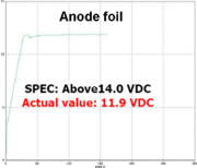 Breakdown voltage of a 10 V rated anode. The specification was >14 V, but in a failed electrolytic capacitor the breakdown voltage measured 11.9 V
 -
 Breakdown voltage of the minimal aluminum oxide dielectric on the cathode of an electrolytic capacitor (see "High ripple current and temperature")
 -
 Anomalous capacitance curve (red), found in a life test, due to increase of water-driven corrosion


Under normal conditions no significant difference could be measured between electrolytic capacitors with water-based electrolytes and e-caps with organic or borax electrolytes. The electrical parameters are stable within their specified values.
This changes with the faulty electrolytic capacitors equipped with the insufficient electrolyte. As shown in the Hillman/Helmold report the electrolyte was into the alkaline pH range. Any pinhole defects that causes a leakage current couldn't repaired anymore because the process of dielectric self-healing ends after the formation of aluminum hydroxide. The subsequent conversion into stable aluminum oxide is prevented by the alkaline environment. The pinhole defects that cause the leakage current remain. Therefore, the leakage current of faulty capacitors was measurable higher than for capacitors with good electrolytes.[34]
The insufficient electrolyte of the faulty capacitors with his alkaline pH value causes also a dissolution of aluminum oxide into the electrolyte. This is connected with a thinning of the dielectric layer. A thinner dielectric reduced the breakdown voltage of the oxide layer. However, the thinning of oxide layer is limited to the voltage applied during operating, which is usually lower than the rated voltage. The decreased dielectric breakdown voltage of the anode can be measured. Pictured above, a typical measurement result is shown. The reduced dielectric breakdown voltage compared to the original anode breakdown voltage shows that a chemical process has caused a thinning of the oxide layer of the anode. This thinner dielectric layer means according to the formula of the plate capacitor,

with the permittivity "ε", the electrode surface "A" and the distance between the electrodes to each other "d", that the capacitance value increases with a thinner dielectric. And indeed, electrolytic capacitors at the beginning of the fatal continual growth of hydroxide, showing a little bulging of the can but with the vent not yet open, exhibit sometimes an increased capacitance value. This temporary increase can be measured, as shown in the red-colored anomalous capacitance curve in the life test in the picture above. The final stage of this process is reached when the hydrogen gas generated by the constant continual growth of aluminum hydroxide has increased to such a high pressure that the vent pops open or the sealing rubber is expelled. Simply said, the capacitor bursts, whether quietly or catastrophically. Once the capacitor has opened its vent, it dries out very quickly, and drops its capacitance down to a minimum value while the ESR increases significantly up to the kilohm range. Because the ripple current still flows through the capacitor's now-higher ESR, the heat losses grow, rapidly increasing the temperature of the electrodes up to an overheat situation, and discoloring the paper separator to brown. Additional with reduced capacitance value the discharging currents increases the cathode voltage, so that besides this an increased value of the cathode breakdown voltage is measurable.
Autopsy of failed electrolytic capacitors
-
 Capacitor with open vent
 -
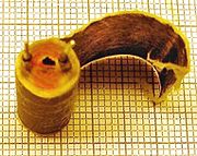 Opened electrolytic capacitor with extracted foils partly unwound. Red color is typical for the faulty water-based electrolyte chemistries.
 -
 Unwound layers of a failed electrolytic capacitor; aluminum foils and paper spacer are glued together. No obvious damage (short circuit) is visible.


Faulty electrolytic capacitors with the insufficient water-based electrolytes often show the same symptoms of bulged cans, open vents or expelled rubber plugs. The opend electrolytic capacitor with extracted foils often are red colored. The unwound layers of a failed electrolytic capacitor mostly have aluminum foils, which are glued together with the paper spacer. A very special sign is that no obvious damage (burnt spot) due to a short circuit is visible.
of unused and failed electrolytic capacitors
-
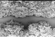
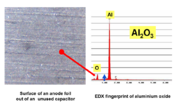 Unused 470 µF/10 V electrolytic capacitor with an intact surface of aluminum oxide; grooves show the direction of the foil during manufacturing (microscopic image, magnification 10x)
 -
 Failed 470 µF/10 V electrolytic capacitor; grooves from manufacturing are still visible, but the surface is coated with plate-like aluminum hydroxide (microscopic image, magnification 10x)


Open the failed capacitors and unwound the windings the anode and the cathode foils can be analyzed. Even in a microscopic image with only 10-fold magnification, as shown in the pictures above, a significant change in the structure of the anode surface between “fresh” and used capacitors is visible. On the surface of the "fresh" anode from an unused electrolytic capacitor the parallel scratches from manufacturing processing of the anode are clearly visible. However, the enlargement in the pictures left is not sufficient to show the openings of the pores in the anode, which are visible using a scanning electron microscope (SEM) in the following pictures. An EDX-fingerprint analysis showed the chemical difference in the surface oxide between “fresh” and used anode. The aluminum hydroxide is proved by the enlarged oxide peak.
of unused and failed electrolytic capacitors
-
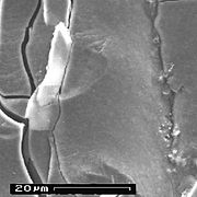
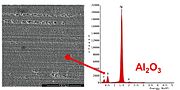 SEM image of an unused anode surface from a 1000 uF/10 V electrolytic capacitor; the pore openings in the anode are clearly visible, the surface is covered with aluminum oxide.
 -
 SEM image of anode surface from a failed 1000 uF/10 V electrolytic capacitor; aluminum hydroxide has overgrown all structures on the anode.


Also in the SEM images on the surface of the "fresh" anode from an unused electrolytic capacitor the parallel scratches from manufacturing processing of the anode are clearly visible. Additional the SEM image show the pores in the anode. In the picture of the used anode, which comes from a failed capacitor with insufficient electrolyte, this surface is overgrown with a plaque-like substance transverse to the running direction of the scratches. An EDX-fingerprint analysis showed the chemical difference in the surface oxide. The surface of the "fresh" electrolytic capacitor was covered with stable aluminum oxide. The surface of the failed capacitor was covered with unstable aluminum hydroxide; the EDX scan shows a significantly higher oxygen peak.
Additional remarks
Capacitor plagues ending
The first publicized press releases about the widespread problem with premature failures of Taiwanese electrolytic capacitors appeared in September 2002. It might be assumed that by mid-2003 the affected capacitor manufacturers would have changed their production process and used a "correct" electrolyte mixture. With a typical shortened life span of about 1.5 to 3 years for the failing capacitors from mid-2003 up to mid-2006, the last of the bad capacitors should have failed by 2007. Commentators on the Internet often predicted the year 2007 would be the end point for "bad capacitors".
Continuing failures
Electrolytic capacitors get produced in billions of pieces every year. It is simple naturally that failing capacitors occur at every time. New complaints about failed capacitors are reported on the Internet very quickly. However, only a carefully analysis in every single case can deliver the reason for failing. Since 2007 no carful analyzed “insufficient water-based electrolyte” would be found and reported on the Internet, even if the appearance of faulty capacitors shown may be similar to those of the capacitor plague case.
Date of manufacture code
Many manufacturers use a 2-character abbreviation according to the
- First character: Year of production, M = 2000, N = 2001, P = 2002,R = 2003, S = 2004, T = 2005, U = 2006, V = 2007, W = 2008, X = 2009, A = 2010, B = 2011, C = 2012, D = 2013, E = 2014
- Second character: Month of production, 1 to 9 = Jan. to Sept., O = Oct., N = Nov., D = Dec
Example: X8 = August 2009
References
- ^ a b c d e D. M. Zogbi, Paumanok Publications, Low-ESR Aluminum Electrolytic Failures Linked to Taiwanese Raw Material Problems, PASSIVE COMPONENTINDUSTRY SEPTEMBER/OCTOBER 2002, page 10, 12, 31 [1] or PDF
- ^ a b The Capacitor Plague, Posted on November 26, 2010 by PC Tools [http://www.pctools.com/security-news/faulty-capacitors/)
- ^ Sperling, Ed; Soderstrom, Thomas; Holzman, Carey (October 2002). "Got Juice?". EE Times.
- ^ )
- ^ Carey Holzman, Overclockers, Capacitors: Not Just For Abit Owners, Motherboards with leaking capacitors, 10/9, 2002, [2]
- ^ a b "Motherboard Capacitor Problem Blows Up". Silicon Chip. AU. 2003-05-11. Retrieved 2012-03-07.
- ^ P. Hales, the Inquirer, Nov 05 2002, Taiwanese component problems may cause mass recalls, Faulty capacitors may afflict mobos, modems [3]
- ^ Capacitor failures plague motherboard vendors, GEEK, Feb. 7, 2003 [4]
- ^ "Bad Capacitors: Information and symptoms". Lowyat.
- ^ Badcaps.net [5]
- ^ W. BONOMO, G. HOOPER, D. RICHARDSON, D. ROBERTS, and TH. VAN DE STEEG, Vishay Intertechnology, Failure modes in capacitors, [6]
- ^ "Mainboardhersteller steht für Elko-Ausfall gerade", Heise (in German) (online ed.), DE.
- ^ Michael Singer , CNET News, Bulging capacitors haunt Dell, October 31, 2005 [7]
- ^ Michael Singer, CNET News, PCs plagued by bad capacitors [8]
- ^ The guardian technology blog, How a stolen capacitor formula ended up costing Dell $300m [9]
- ^ Vance, Ashlee (June 28, 2010). "Suit Over Faulty Computers Highlights Dell's Decline". The New York Times. Retrieved 2012-03-08.
- ^ Capacitor Replacement Video Tutorial (HD) (video), Afro tech mods.
- ^ Repair and bad capacitor information, Capacitor Lab.
- ^ The Aluminum Electrolytic Condenser, H. 0. Siegmund, Bell System Technical Journal, v8, 1. January 1229, pp. 41 -63
- ^ A. Güntherschulze, H. Betz, Elektrolytkondensatoren, Verlag Herbert Cram, Berlin, 2. Auflage 1952
- ^ a b "A. Albertsen, Electrolytic Capacitor Lifetime Estimation" (PDF). Retrieved 2014-09-04.
- ^ a b Sam G. Parler, Cornell Dubilier, Deriving Life Multipliers for Electrolytic Capacitors [10]
- ^ a b B. Liotta, “Taiwanese Cap Makers Deny Responsibility,” Passive Component Industry, Nov/Dec 2002, p. 6, 8-10 PDF
- ^ "Capacitor plague, identifizierte Hersteller (~identified vendors)". Opencircuits.com. 2012-01-10. Retrieved 2014-09-03.
- ^ Sundoc Bibliothek, Universität Halle, Dissertation, Aluminum anodization, [11]
- ^ Elna, Principles, 3. Electrolyte, Table 2: An Example of the Composition of the Electrolyte [12]
- ^ NON-AQUEOUS ELECTROLYTES and THEIR CHARACTERISTICS, FaradNet Electrolytic Capacitors, Part III: Chapter 10 [13]
- ^ K. H. Thiesbürger: Der Elektrolyt-Kondensator. 4. Auflage. Roederstein, Landshut 1991, [OCLC31349250]
- ^ W. J. Bernard, J. J. Randall Jr., The Reaction between Anodic Aluminum Oxide and Water, [14]
- ^ Ch. Vargel, M. Jacques, M. P. Schmidt, Corrosion of Aluminium, 2004 Elsevier B.V., ISBN: 978-0-08-044495-6
- ^ a b Alfonso Berduque, Zongli Dou, Rong Xu, BHC Components Ltd (KEMET), Electrochemical Studies for Aluminium Electrolytic Capacitor Applications: Corrosion Analysis of Aluminium in Ethylene Glycol-Based Electrolytes [15]
- ^ "Alu Encyclopaedia, oxide layer". Aluinfo.de. Retrieved 2014-09-04.
- ^ J. M. Sanz, J. M. Albella, J. M. Martinez-Duart, On the inhibition of the reaction between anodic aluminum oxide and water [16]
- ^ a b c d Hillman; Helmold (2004), Identification of Missing or Insufficient Electrolyte Constituents in Failed Aluminum Electrolytic Capacitors (PDF), DFR solutions Cite error: The named reference "HHpaper" was defined multiple times with different content (see the help page).
- ^ K. H. Thiesbürger: Der Elektrolyt-Kondensator. 4th edition, Page 88 to 91,Roederstein, Landshut 1991 (OCLC 313492506)
- ^ H. Kaesche, Die Korrosion der Metalle - Physikalisch-chemische Prinzipien und aktuelle Probleme, Springer-Verlag, Berlin, 1966, ISBN: 978364184277
- ^ Shigeru Uzawa, Akihiko Komat-u, Tetsushi Ogawara, Rubycon Corporation, Ultra Low Impedance Aluminum Electrolytic Capacitor with Water based Electrolyte
- ^ J.L. Stevens, T. R. Marshall, A.C. Geiculescu m, C.R. Feger, T.F. Strange, Carts USA 2006, The Effects of Electrolyte Composition on the Deformation Characteristics of Wet Aluminum ICD Capacitors, [17]
- ^ J. Vereecken, Corrosion Control of Aluminium -Forms of Corrosion and Prevention, J. Electrochem. Soc. 1961 volume 108, issue 9, 822-825m, doi: 10.1149/1.2428230 [18]
- ^ "Rubycon". Rubycon. Retrieved 2014-09-04.
- ^ Shigeru Uzawa, Akihiko Komatsu, Tetsushi Ogawara, Rubycon Corporation, Ultra Low Impedance Aluminum Electrolytic Capacitor with Water based Electrolyte. Journal of Reliability Engineering Association of Japan Accession number;02A0509168, ISSN:0919-2697, [dead link]
- ^ "Ncc, Ecc". Chemi-con.co.jp. Retrieved 2014-09-04.
- ^ "Nichicon". Nichicon-us.com. Retrieved 2014-09-04.
- ^ "Elna". Elna. Retrieved 2014-09-04.
- ^ Low-ESR Aluminium Electrolytic Failures Linked to Taiwanese Raw Material Problems (PDF), Molalla.
- ^ Chang, Jeng-Kuei, Liao, Chi-Min, Chen, Chih-Hsiung, Tsai, Wen-Ta, Effect of electrolyte composition on hydration resistance of anodized aluminum oxide [19]