
Physics of optical holography
Optical holography[1] is a technique which enables an optical wavefront to be recorded and later re-constructed. Holography is best known as a method of generating three-dimensional images but it also has a wide range of other applications.
A
Basic physics
To understand the process, it is helpful to understand
For those unfamiliar with these concepts, it is worthwhile to read those articles before reading further in this article.
A simple hologram
The recorded light pattern is a diffraction grating, which is a structure with a repeating pattern. A simple example is a metal plate with slits cut at regular intervals. A light wave that is incident on a grating is split into several waves; the direction of these diffracted waves is determined by the grating spacing and the wavelength of the light.
When the recorded light pattern is illuminated by only one of the plane waves used to create it, it can be shown that one of the diffracted waves is a re-construction of the other plane wave.

When a plane wave is added to a point source and the resulting interference pattern recorded, a point source hologram is produced. This is effectively a Fresnel zone plate which acts as a lens. If the plane wave is normally incident on the recording plate, three waves are diffracted by the plate
- the original plane wave
- a wave which appears to diverge from the point source - this is a reconstruction of the original point source wave
- a wave which is focused to a point on the other side of the plate at the same distance as the original point source
This is known as an in-line hologram. Its usefulness is limited by the fact that all three waves are superimposed.
If the plane wave illuminates the recording plate at non-normal incidence, then the three diffracted waves are now as follows:
- the original plane wave
- a wave which appears to diverge from the original point source - this is the re-constructed wave
- a wave which converges to a point which is deflected from the normal by twice the angle of incidence of the plane wave - this is known as the conjugate wave.
The three waves are now separated in space. This is known as an off-axis hologram. It was first developed by Leith and Upatnieks[4] and was a vital step in enabling 3-d images to be produced with holography.
Theory underlying the holographic process
General form
The
![{\displaystyle \mathbf {U} (\mathbf {r} )=A\exp {i[\varphi (\mathbf {r} )]}}](https://wikimedia.org/api/rest_v1/media/math/render/svg/20545ce2a970f844e56d1a30e110dddc1c46cf9b)
where A represents the amplitude of the vector, and its phase.

To make a hologram, two waves are added together to give a total complex amplitude which can be represented as

where R refers to the recording wavefront, known as the reference wavefront, and O refer to the wavefront being recorded. The dependence on r has been omitted for clarity.
The intensity of the combined beams is the average value of the complex amplitude times its complex conjugate:

A recording medium is exposed to the two beams and then developed. Assume that the amplitude transmittance, of the developed photographic plate is linearly related to the intensity of the interference pattern.

![{\displaystyle \mathbf {t} =\mathbf {t} _{0}+\beta \left[A_{\text{R}}^{2}+A_{\text{O}}^{2}+A_{\text{R}}A_{\text{O}}\exp {i(\varphi _{\text{R}}-\varphi _{\text{O}})}+A_{\text{R}}A_{\text{O}}\exp {-i(\varphi _{\text{R}}-\varphi _{\text{O}})}\right]}](https://wikimedia.org/api/rest_v1/media/math/render/svg/a2d466d9e8dcaddf7a56618f26915619e2cea1b3)
where is a constant background transmittance and is constant,


When the developed photographic plate is illuminated only by the reference beam, , the amplitude of the light transmitted through the plate, UH, is given by

![{\displaystyle \mathbf {U} _{H}=\mathbf {t} A_{\text{R}}\exp {i\varphi _{\text{R}}}=\left[\mathbf {t} _{0}+\beta \left[A_{\text{R}}^{2}+A_{\text{O}}^{2}+A_{\text{R}}A_{\text{O}}\exp {i(\varphi _{\text{R}}-\varphi _{\text{O}})}+A_{\text{R}}A_{\text{O}}\exp {-i(\varphi _{\text{R}}-\varphi _{\text{O}})}\right]\right]A_{\text{R}}\exp {i\varphi _{\text{R}}}}](https://wikimedia.org/api/rest_v1/media/math/render/svg/6465f016185065e19168aefb90fb7c5cd3798011)
This can be split into three terms:[3] : Section 3.5.2
![{\displaystyle {\begin{aligned}\mathbf {U} _{1}&=\left[\mathbf {t} _{0}+\beta A_{\text{R}}^{2}+\beta A_{\text{O}}^{2}\right]A_{\text{R}}\exp {i\varphi _{\text{R}}}\\\mathbf {U} _{2}&=\beta A_{\text{R}}^{2}A_{\text{O}}\exp i\varphi _{\text{O}}\\\mathbf {U} _{3}&=\beta A_{\text{R}}^{2}A_{\text{O}}\exp {i(2\varphi _{\text{R}}-\varphi _{\text{O}})}\end{aligned}}}](https://wikimedia.org/api/rest_v1/media/math/render/svg/1fbcf778050aeda922f59d18d87f3e13d59abf3c)
is a modified version of the reference wave. The first term is a reduced amplitude version, the second is also a reduced amplitude version if the reference wave amplitude is uniform. The third term produces a halo round the transmitted reference wave which is negligible when the amplitude of the object wave is much less than that of the reference wave

is the reconstructed object wave which is identical to the original wave except that its amplitude is reduced. When the object wave is generated by light scattered from an object or objects, a virtual image of the object(s) is formed when a lens is placed in the reconstructed wave.

is known as the conjugate wave. It is similar to the object wave but has the opposite curvature. When the object wave is generated by light scattered from an object or a series of objects, a real image is formed on the opposite side of the hologram plate to where the object was located and is deflected from the normal axis by twice the angle between the reference wave and the normal direction.[2]: Section 1.2. Section 2.2

Two plane waves

The reference and object wave are monochromatic plane waves of uniform amplitude[3]: 1.4
![{\displaystyle {\begin{aligned}\mathbf {U_{\text{R}}} (\mathbf {r} )&=A_{\text{R}}\exp \left[i\mathbf {k_{\text{R}}} \cdot \mathbf {r} \right]\\\mathbf {U_{\text{O}}} (\mathbf {r} )&=A_{\text{O}}\exp \left[i\mathbf {k_{\text{O}}} \cdot \mathbf {r} \right]\end{aligned}}}](https://wikimedia.org/api/rest_v1/media/math/render/svg/34eee46314891ec5135b7c427e771bb0676b850f)
where the vectors are related to the unit vectors which define the direction of travel and the wavelength of the two waves by


The expression for in the previous section can be written as
![{\displaystyle \mathbf {t} =\mathbf {t} _{0}+\beta \left[A_{\text{O}}^{2}+A_{\text{R}}^{2}+A_{\text{O}}A_{\text{R}}\cos {\left([\mathbf {k_{O}} -\mathbf {k_{R}} ]\cdot \mathbf {r} \right)}\right]}](https://wikimedia.org/api/rest_v1/media/math/render/svg/4e1c1a91ca52aea1320a625fa0b24cdc7e369823)
from which it can be seen that the transmission of the holographic recording varies sinusoidally, i.e.it is a diffraction grating, where spacing of the fringes depends on the angle between the two waves and the orientation of the holographic plate.
The reconstructed wave is:

which is a plane wave travelling in the direction , i.e. it is the reconstructed object wave with a modified amplitude.

The conjugate wave is:
![{\displaystyle \mathbf {U} _{3}=A_{\text{O}}A_{\text{R}}\exp[i(2\mathbf {k} _{R}-\mathbf {k} _{O})\cdot \mathbf {r} ]}](https://wikimedia.org/api/rest_v1/media/math/render/svg/a0cd1c20124dd6a8125d1b024838005e4fdf9382)
which is a plane wave travelling in the direction

This shows that the transmission of the photographic plate varies sinusoidally so it acts as a diffraction grating. If one of the waves is normally incident to the hologram plate, and the other is incident at an angle , the spacing of the fringes is and the first order diffracted waves will be at angles given by . One of these is the reconstructed object plane wave, the other is the conjugate wave.


Plane wave and point source

Consider a point source located at the origin which illuminates a photographic plate which is located at a distance normal to the z axis. The phase difference between the source and a point (x, y, z) is given approximately by[1]: 3.1


where

The complex amplitude of the object beam is then given by
- .

The form of the interference pattern for various directions of incidence for the reference wave are shown on the right.
The reference plane wave is
![{\displaystyle \mathbf {U_{\text{R}}} (\mathbf {r} )=A_{\text{R}}\exp[i\mathbf {k_{\text{R}}} \cdot \mathbf {r} ]}](https://wikimedia.org/api/rest_v1/media/math/render/svg/15d8dba13951d20a066feef36e4e03d8176ee148)
The reconstructed wave is described by the second term:

The conjugate wave is described by the third term

It emerges at twice the angle between the object and references wave and converges to a point which is at the same distance from the plate as the original point source.[1] : Section 2.2
General object and a point source

When light is scattered off a general object, the amplitude of the scattered light at any point can be represented by

![{\displaystyle \mathbf {U_{\text{O}}} (\mathbf {r} )=A_{\text{O}}(\mathbf {r} )\exp {i[\varphi _{\text{O}}(\mathbf {r} )]}}](https://wikimedia.org/api/rest_v1/media/math/render/svg/7fc321d46442c6aacc77500cbedbeb2695e0d072)
where both the phase and the amplitude vary with .

The distance travelled by a wave emitted from a point source located at a point to a point travels a distance , so that the phase change is so that its amplitude is given by


where is constant.

The reconstructed object wave is
![{\displaystyle \mathbf {U} _{2}=\beta A_{\text{R}}^{2}A_{\text{O}}(\mathbf {r} )\exp {i[\varphi _{\text{O}}(\mathbf {r} )]}}](https://wikimedia.org/api/rest_v1/media/math/render/svg/b941e1be422281e05532f18ebb789a73fafdcfe7)
The conjugate wave is given by

Recording a hologram
Items required

To make a hologram, the following are required:[1]: Sections 5.1, 5.8, 7.1 [3]: Chapter 5 [6]
- a suitable object or set of objects
- part of the laser beam to be directed so that it illuminates the object (the object beam) and another part so that it illuminates the recording medium directly (the reference beam), enabling the reference beam and the light which is scattered from the object onto the recording medium to form an interference pattern
- a recording medium which converts this interference pattern into an optical element which modifies either the amplitude or the phase of an incident light beam according to the intensity of the interference pattern.
- a laser beam that produces coherent light with one wavelength.
- an environment which provides sufficient mechanical and thermal stability that the interference pattern is stable during the time in which the interference pattern is recorded.
These requirements are inter-related, and it is essential to understand the nature of optical interference to see this.
The exposure time required to record the hologram depends on the laser power available, on the particular medium used and on the size and nature of the object(s) to be recorded, just as in conventional photography. This determines the stability requirements. Exposure times of several minutes are typical when using quite powerful gas lasers and silver halide emulsions. All the elements within the optical system have to be stable to fractions of a μm over that period. It is possible to make holograms of much less stable objects by using a
Thus, the laser power, recording medium sensitivity, recording time and mechanical and thermal stability requirements are all interlinked. Generally, the smaller the object, the more compact the optical layout, so that the stability requirements are significantly less than when making holograms of large objects.
Another very important laser parameter is its coherence.[2]: Section 4.2, p40 This can be envisaged by considering a laser producing a sine wave whose frequency drifts over time; the coherence length can then be considered to be the distance over which it maintains a single frequency. This is important because two waves of different frequencies do not produce a stable interference pattern. The coherence length of the laser determines the depth of field which can be recorded in the scene. A good holography laser will typically have a coherence length of several meters, ample for a deep hologram.
The objects that form the scene must, in general, have optically rough surfaces so that they scatter light over a wide range of angles. A specularly reflecting (or shiny) surface reflects the light in only one direction at each point on its surface, so in general, most of the light will not be incident on the recording medium. A hologram of a shiny object can be made by locating it very close to the recording plate.
Hologram classifications
There are three important properties of a hologram which are defined in this section. A given hologram will have one or other of each of these three properties, e.g. an amplitude modulated, thin, transmission hologram, or a phase modulated, volume, reflection hologram.
Amplitude and phase modulation holograms
An amplitude modulation hologram[3]: Section 3.5.3 is one where the amplitude of light diffracted by the hologram is proportional to the intensity of the recorded light. A straightforward example of this is photographic emulsion on a transparent substrate. The emulsion is exposed to the interference pattern, and is subsequently developed giving a transmittance which varies with the intensity of the pattern – the more light that fell on the plate at a given point, the darker the developed plate at that point.
A phase hologram
Thin holograms and thick (volume) holograms
A thin hologram[1]: Section 4.1 is one where the thickness of the recording medium is much less than the spacing of the interference fringes which make up the holographic recording. The thickness of a thin hologram can be down to 60 nm by using a topological insulator material Sb2Te3 thin film.[9] Ultrathin holograms hold the potential to be integrated with everyday consumer electronics like smartphones.
A thick or volume hologram[1]: Section 4.2 is one where the thickness of the recording medium is greater than the spacing of the interference pattern. The recorded hologram is now a three dimensional structure, and it can be shown that incident light is diffracted by the grating only at a particular angle, known as the Bragg angle.[10] If the hologram is illuminated with a light source incident at the original reference beam angle but a broad spectrum of wavelengths; reconstruction occurs only at the wavelength of the original laser used. If the angle of illumination is changed, reconstruction will occur at a different wavelength and the colour of the re-constructed scene changes. A volume hologram effectively acts as a colour filter.
Transmission and reflection holograms
A transmission hologram is one where the object and reference beams are incident on the recording medium from the same side. In practice, several more mirrors may be used to direct the beams in the required directions.
Normally, transmission holograms[3]: Section 4.3.1 can only be reconstructed using a laser or a quasi-monochromatic source, but a particular type of transmission hologram, known as a rainbow hologram, can be viewed with white light.
In a reflection hologram,[3]: Section 4.3.2 the object and reference beams are incident on the plate from opposite sides of the plate. The reconstructed object is then viewed from the same side of the plate as that at which the re-constructing beam is incident.
Only volume holograms can be used to make reflection holograms, as only a very low intensity diffracted beam would be reflected by a thin hologram.
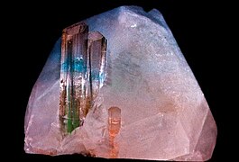
Examples of full-color reflection holograms of mineral specimens:
-
 Hologram of Elbaite on Quartz
 -
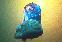 Hologram of Tanzanite on Matrix
 -
 Hologram of Tourmaline on Quartz
 -
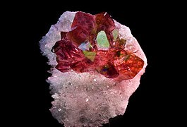 Hologram of Amethyst on Quartz


Holographic recording media
The recording medium has to convert the original interference pattern into an optical element that modifies either the amplitude or the phase of an incident light beam in proportion to the intensity of the original light field.
The recording medium should be able to resolve fully all the fringes arising from interference between object and reference beam. These fringe spacings can range from tens of
If the response is not flat over the range of spatial frequencies in the interference pattern, then the resolution of the reconstructed image may also be degraded.,[2]: Section 6.4, p88 [12]
The table below shows the principal materials used for holographic recording. Note that these do not include the materials used in the
| Material | Reusable | Processing | Type | Theoretical max. efficiency | Required exposure (mJ/cm2) | Resolution limit (mm−1) |
|---|---|---|---|---|---|---|
| Photographic emulsions | No | Wet | Amplitude | 6% | 1.5 | 5000 |
| Phase (bleached) | 60% | |||||
| Dichromated gelatin | No | Wet | Phase | 100% | 100 | 10,000 |
| Photoresists | No | Wet | Phase | 30% | 100 | 3,000 |
| Photothermoplastics | Yes | Charge and heat | Phase | 33% | 0.1 | 500–1,200 |
| Photopolymers | No | Post exposure | Phase | 100% | 10000 | 5,000 |
| Photorefractives | Yes | None | Phase | 100% | 10 | 10,000 |
Copying and mass production
An existing hologram can be copied by embossing[13] or optically.[2] : Section 11.4.1, p191
Most holographic recordings (e.g. bleached silver halide, photoresist, and photopolymers) have surface relief patterns which conform with the original illumination intensity. Embossing, which is similar to the method used to stamp out plastic discs from a master in audio recording, involves copying this surface relief pattern by impressing it onto another material.
The first step in the embossing process is to make a stamper by electrodeposition of nickel on the relief image recorded on the photoresist or photothermoplastic. When the nickel layer is thick enough, it is separated from the master hologram and mounted on a metal backing plate. The material used to make embossed copies consists of a polyester base film, a resin separation layer and a thermoplastic film constituting the holographic layer.
The embossing process can be carried out with a simple heated press. The bottom layer of the duplicating film (the thermoplastic layer) is heated above its softening point and pressed against the stamper, so that it takes up its shape. This shape is retained when the film is cooled and removed from the press. In order to permit the viewing of embossed holograms in reflection, an additional reflecting layer of aluminum is usually added on the hologram recording layer. This method is particularly suited to mass production.
The first book to feature a hologram on the front cover was
It is possible to print holograms directly into steel using a sheet explosive charge to create the required surface relief.[15] The Royal Canadian Mint produces holographic gold and silver coinage through a complex stamping process.[16]
A hologram can be copied optically by illuminating it with a laser beam, and locating a second hologram plate so that it is illuminated both by the reconstructed object beam, and the illuminating beam. Stability and coherence requirements are significantly reduced if the two plates are located very close together.[17] An index matching fluid is often used between the plates to minimize spurious interference between the plates. Uniform illumination can be obtained by scanning point-by-point or with a beam shaped into a thin line.
Reconstructing and viewing the holographic image

When the hologram plate is illuminated by a laser beam identical to the reference beam which was used to record the hologram, an exact reconstruction of the original object wavefront is obtained. An imaging system (an eye or a camera) located in the reconstructed beam 'sees' exactly the same scene as it would have done when viewing the original. When the lens is moved, the image changes in the same way as it would have done when the object was in place. If several objects were present when the hologram was recorded, the reconstructed objects move relative to one another, i.e. exhibit parallax, in the same way as the original objects would have done. It was very common in the early days of holography to use a chess board as the object and then take photographs at several different angles using the reconstructed light to show how the relative positions of the chess pieces appeared to change.
A holographic image can also be obtained using a different laser beam configuration to the original recording object beam, but the reconstructed image will not match the original exactly.
White light consists of light of a wide range of wavelengths. Normally, if a hologram is illuminated by a white light source, each wavelength can be considered to generate its own holographic reconstruction, and these will vary in size, angle, and distance. These will be superimposed, and the summed image will wipe out any information about the original scene, as if superimposing a set of photographs of the same object of different sizes and orientations. However, a holographic image can be obtained using white light in specific circumstances, e.g. with volume holograms and rainbow holograms. The white light source used to view these holograms should always approximate to a point source, i.e. a spot light or the sun. An extended source (e.g. a fluorescent lamp) will not reconstruct a hologram since its light is incident at each point at a wide range of angles, giving multiple reconstructions which will "wipe" one another out.
White light reconstructions do not contain speckles.
Volume holograms
A reflection-type volume hologram can give an acceptably clear reconstructed image using a white light source, as the hologram structure itself effectively filters out light of wavelengths outside a relatively narrow range. In theory, the result should be an image of approximately the same colour as the laser light used to make the hologram. In practice, with recording media that require chemical processing, there is typically a compaction of the structure due to the processing and a consequent colour shift to a shorter wavelength. Such a hologram recorded in a silver halide gelatin emulsion by red laser light will usually display a green image. Deliberate temporary alteration of the emulsion thickness before exposure, or permanent alteration after processing, has been used by artists to produce unusual colours and multicoloured effects.
Rainbow holograms

In this method, parallax in the vertical plane is sacrificed to allow a bright, well-defined, gradiently colored reconstructed image to be obtained using white light. The rainbow holography recording process usually begins with a standard transmission hologram and copies it using a horizontal slit to eliminate vertical parallax in the output image. The viewer is therefore effectively viewing the holographic image through a narrow horizontal slit, but the slit has been expanded into a window by the same dispersion that would otherwise smear the entire image. Horizontal parallax information is preserved but movement in the vertical direction results in a color shift rather than altered vertical perspective.[2]: Section 7.4 Because perspective effects are reproduced along one axis only, the subject will appear variously stretched or squashed when the hologram is not viewed at an optimum distance; this distortion may go unnoticed when there is not much depth, but can be severe when the distance of the subject from the plane of the hologram is very substantial. Stereopsis and horizontal motion parallax, two relatively powerful cues to depth, are preserved.
The holograms found on
Fidelity of the reconstructed beam

To replicate the original object beam exactly, the reconstructing reference beam must be identical to the original reference beam and the recording medium must be able to fully resolve the interference pattern formed between the object and reference beams.
Any change in the shape, orientation or wavelength of the reference beam gives rise to aberrations in the reconstructed image. For instance, the reconstructed image is magnified if the laser used to reconstruct the hologram has a longer wavelength than the original laser. Nonetheless, good reconstruction is obtained using a laser of a different wavelength, quasi-monochromatic light or white light, in the right circumstances.
Since each point in the object illuminates all of the hologram, the whole object can be reconstructed from a small part of the hologram. Thus, a hologram can be broken up into small pieces and each one will enable the whole of the original object to be imaged. One does, however, lose information and the spatial resolution gets worse as the size of the hologram is decreased – the image becomes "fuzzier". The field of view is also reduced, and the viewer will have to change position to see different parts of the scene.
References
- ^ ISBN 9780521433488.
- ^ ISBN 9780511755569.
- ^ ISBN 9780429192142.
- .
- ISBN 0-521-64222-1.
- ^ Wilson, Tracy V. "How Holograms Work". How Stuff Works. Retrieved 3 April 2021.
- PMID 20836549.
- ^ "Photograph of Dennis Gabor standing beside his holographic portrait". MIT. Archived from the original on 27 September 2012. Retrieved 2011-09-16.
- PMID 28516906.
- ^ Lipson, (2011), Section 12.5.4, p443
- ^ "Kodak black and white professional film|" (PDF). Retrieved 2011-09-14.
- ^ Kozma A & Zelenka JS, (1970), Effect of film resolution and size in holography, Journal of the Optical Society of America, 60, 34–43
- PMID 20126192.
- ^ "Hologram on National Geographic Magazine Cover". Smithsonian.
- ^ "Holograms with explosive power". Physorg.com. Retrieved 2012-04-21.
- ^ "Lunar Holographic Coins". Retrieved 2011-09-14.
- ^ Harris JR, Sherman GC and Billings BH, 1966, Copying hologram, Applied Optics, 5, 665–6
- ^ S. Koreshev, A. Gromov, O. Nikanorov, "Modernized Software Complex for Synthesis and Reconstruction of Fresnel Holograms-Projectors", Scientific and Technical Journal of Information Technologies, Mechanics and Optics, Number 6, Volume 12, 2012