
Space Launch System core stage
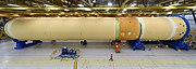
 The Artemis 1 Core Stage horizontal in the Vehicle Assembly Building | |
| Manufacturer | Boeing |
|---|---|
| Country of origin | United States |
| Used on | Space Launch System |
| General characteristics | |
| Height | 65 m (212 ft)[1] |
| Diameter | 8.4 m (27.6 ft)[1] |
| Propellant mass | 987 t (2,177,000 lb) [1] (144 t (317,000 lb) LH2, 840 t (1,860,000 lb) LOx[1]) |
| Empty mass | 88,275 kg (194,613 lb)[1] |
| Launch history | |
| Status | Active |
| Total launches | 1 |
| Successes (stage only) | 1 |
| First flight | November 16, 2022 (Artemis 1) |
| Engine details | |
| Powered by | 4 RS-25 |
| Maximum thrust | 9,120 kN (2,050,000 lbf) |
| Specific impulse | 366 seconds (3.59 km/s) sea level, 452.3 seconds (4.436 km/s) vacuum |
| Burn time | 500 s[2] |
| Propellant | LH2/LOX |
The Space Launch System core stage, or simply core stage, is the main stage of the American Space Launch System (SLS) rocket, built by The Boeing Company in the NASA Michoud Assembly Facility. At 65 m (212 ft) tall and 8.4 m (27.6 ft) in diameter, the core stage contains approximately 987 t (2,177,000 lb) of its liquid hydrogen and liquid oxygen cryogenic propellants. Propelled by 4 RS-25 engines, the stage generates approximately 7.44 MN (1,670,000 lbf) of thrust, about 25% of the Space Launch System's thrust at liftoff, for approximately 500 seconds, propelling the stage alone for the last 375 seconds of flight. The stage lifts the rocket to an altitude of approximately 162 km (531,380 ft) before separating, reentering the atmosphere, and splashing down in the Pacific Ocean.
The core stage originated in 2011, when the architecture of the Space Launch System as a whole was defined. In the aftermath of the end of the Space Shuttle program and the cancellation of its prospective replacement the Constellation program, the SLS emerged, a super-heavy lift launch vehicle intended for human spaceflight to the Moon.[3] The core stage is the first newly-developed stage of the SLS; the ICPS (Interim Cryogenic Propulsion Stage) and five-segment boosters are adaptations of existing hardware, to be replaced by the Exploration Upper Stage and BOLE boosters respectively.
Production of core stages began by 2014, but was beset by numerous difficulties in production and testing which delayed the readiness of the first core stage by several years. The core stage first flew on November 16, 2022, on the Artemis 1 mission, in which it performed successfully. As of 2023, the second, third, and fourth core stages are in production, while work has begun for the fifth and sixth, their production pending the transfer of SLS operations to Deep Space Transport, the vehicle's future operator.
Design
The core stage comprises five major sections: the engine section, the liquid hydrogen (LH2) tank, the intertank, the liquid oxygen (LOx) tank, and the forward skirt. These elements can be further divided into ten barrel sections, four domes, and seven rings, together forming the structure of the rocket stage.[4]

Main propulsion

The core stage is powered by 4 RS-25 engines housed inside the engine section at the base of the stage. The engines are associated with the main propulsion system, which support the engines in their operation, allowing them to

Thrust structures
The engine section and intertank of the core stage both feature large thrust structures, which transmit thrust forces (the former from the core stage's RS-25 engines, the latter from the twin boosters of an SLS vehicle) through the vehicle. The engine thrust structure also enables the stage's RS-25 engines to be gimballed. Each engine is mounted an attachment point at the base of the thrust structure, while its hydraulic thrust vectoring system is installed on top of that same structure. The engine section thrust structure is bolted together and attached inside the cylindrical engine section barrel.[6] The intertank thrust beam, mounted with the intertank much higher up on the vehicle, is a single beam, which, in conjunction with the thickened and strengthened bolted structure of the intertank itself, allows the thrust of the solid rocket boosters to be transmitted through the stage.[7]
Propellant tanks

The largest structures of the core stage are its propellant tanks, built to carry approximately 987 tonnes of cryogenic propellants, liquid hydrogen and liquid oxygen. The extremely low cryogenic temperatures of these fluids – −182.8 °C (−297.0 °F) for liquid oxygen and −252.8 °C (−423 °F) for liquid hydrogen – causes substantial shrinkage in the propellant tanks.[8] The liquid hydrogen tank shrinks about 15 cm (6 in) in length and 2.5 cm (1 in) in diameter after being filled, while the liquid oxygen tank's size decreases by 3.8 cm (1.5 in) lengthwise and 1.3 cm (0.5 in) across. Therefore, all hardware attached to the propellant tanks must be mounted using bellows that allow them to flexibly adjust to the shifting size of the propellant tanks.[4]
Space Shuttle heritage and differences
The design of the core stage was intended to make use of knowledge and experience gained from the Space Shuttle program, similarly to the rest of the Space Launch System. This is reflected in aspects such as the rocket's 8.4 m (27.6 ft) diameter, identical to that of the
| SLS core stage (2022–) | SLWT (1998–2010)[11] | LWT (1982–1999)[11] | |
|---|---|---|---|
| Engine section | Yes | No | |
| Propellant capacity | 144 t (317,000 lb) LH2, 840 t (1,860,000 lb) | 105 t (231,000 lb) LH2, 630 t (1,380,000 lb) | |
| Diameter | 8.4 m (27.6 ft) | ||
| Primary structure material | Al-Cu 2219 | Al-Li 2195 | Al-Cu 2219 |
| Joining | Friction stir | Plasma arc, later friction stir | Plasma arc |
| LH2 tank structure | Machined orthogrid
|
T-stiffener | |
| LO2 tank structure | Machined orthogrid | Monocoque | |
| Intertank structure | Integrally machined stiffener | Riveted external stringers, internal frame | |
Manufacturing
The SLS core stage is primarily manufactured by Boeing in the NASA-owned Michoud Assembly Facility in New Orleans, previously the site of Space Shuttle external tank and Saturn V S-IC manufacturing.[12]

.jpg)
A number of tools are used in the primary manufacture of the core stage. These include the Circumferential Dome Weld Tool (CDWT) and Gore Weld Tool (GWD), both used in conjunction with the Enhanced Robotic Weld Tool (ERWT), the Vertical Weld Center (VWC), Segmented Ring Tool (SRT), and Vertical Assembly Center (VAC).[13] These tools are generally designed to enable the friction-stir welding, both self-reacting and conventional, circumferential and linear, of the 2219 aluminium-copper alloy of much of the core stage.[13][10] Additional tools include the floor assembly jig (FAJ)[14] and Intertank Final Assembly Tool (IFAT).[15]
Main structural elements
.jpeg)
The core stage's 2 propellant tanks – the "wet' structures – are each built up from a number of barrels, 2 rings, and 2 domes. A barrel consists of eight vertically, linearly-joined "panels", welded in the VWC. Each dome is manufactured from 12 gore panels, first joined into a gore dome in the GWT, a Y-ring, and an end cap, joined by conventional circumferential friction-stir welds.[16] These elements are assembeld into whole domes in the CDWT.[16] Segmented rings, used to connect domes and barrels and to provide stiffness, are produced using the SRT. These items are then welded together circumferentially in the VAC, starting with a forward dome, then barrels, one by one – 5 for a LH2 tank, 2 for a LOx tank[1] – then the aft dome.[16] With the stiffening rings installed, these elements make up a propellant tank. After initial assembly, tanks undergo testing and remediation. X-ray radiography is used to inspect welds for quality. Any defects in welds are corrected using automated and manual techniques.[16] Substantial technology development was required to enable the self-reacting friction stir welding of the core stage's propellant tanks, as the metal making up their walls was thicker than any previously joined using the technique.[17]
.jpg)
The core stage Intertank is manufactured rather differently to the other elements. A "dry" structure, it is required not only to handle the loads of the core stage itself but also the thrust of the twin Solid Rocket Boosters of the SLS, transmitting these loads. Additionally, as a dry structure, it is not pressurized like the propellant tanks. Accordingly, it features external stiffener ribs and thicker structure,[18] which prohibit the use of welding for assembly; therefore, the intertank is bolted together from eight panels using more than 7500 fasteners.[19] By the time the intertank panels are bolted together, they are pre-painted with protective primer.[20]
A Forward Skirt adapts the core stage to the Launch Vehicle Stage Adapter on SLS Block 1 and the Exploration Upper Stage interstage on SLS Block 2. Considered the least complicated and complex of the "dry" structures, its assembly is more straightforward and takes less time than any of the other main elements of the core stage.[16] The ring panels that make it up its structure, together with adapter ring flanges, are covered in anti-corrosion primer prior to structural assembly.[20]
The Engine Section is the most complex element of the core stage, as well as the Space Launch System as a whole. Procurement of its parts and assembly are the longest-lead items in the manufacture of a core stage,[16] and beginning with CS-3, engine sections are integrated in the Space Station Processing Facility (SSPF) at Kennedy Space Center.[14] Structural assembly of all engine sections takes place in the Michoud Assembly Facility. The structural elements consist of a welded barrel (composed of 8 panels), a mating ring, used to adapt the engine section to the LH2 tank, and a thrust structure, whose structure is bolted. These structures are then aligned in the FAJ, together with certain elements such as brackets for equipment, and bolted together with approximately 2000 fasteners.[14][21] Once primary structural assembly of the engine section is complete, it then enters the "clean" phase of manufacture, during which it is kept in a controlled environment.[14] For engine sections integrated at Michoud Assembly Facility, small enclosures with airlocks were set up surrounding the article, torn down and rebuilt as needed. In contrast, for assembly at the SSPF, the stage is kept in a controlled building with airlock. Here, installation of hardware takes place. Piping for hydraulic and pneumatic systems is joined, as well as ducting for the rocket's cryogenic propellants. Electrical wiring is added and installed to harnesses, and avionics hardware and instrumentation installed. After these line installations are complete, larger subassemblies such as the thrust vector control platforms and helium tanks are lifted into the engine section from above and installed.[14] Additionally, a boattail, the base of the engine section, is installed.[22]
.jpg)
Thermal protection system
After propellant tanks are structurally complete, they undergo a finishing process that protects the structure from corrosion and thermal loads. Each tank is covered with anti-corrosion zinc oxide primer, sprayed on using automated machines.[21] The tanks then are given their spray-on foam thermal protection system, which gives the stage its distinctive orange appearance.[23] This insulation itself is made up of isocyanates and a blend of polyols, separate before application, and mixed in a spray head that allows them to release in the form a foam.[23] The tanks are rotated to a horizontal orientation, where the major surfaces are robotically sprayed with insulation material. While receiving the thermal protection system application, the tanks are rotated at about 2 rotations per minute so as to receive even coverage.[20] All core stages had their barrel sections robotically sprayed; beginning with the second core stage, the tank domes are also robotically sprayed.[21] Automated spraying requires specifically controlled temperature and humidity conditions, while manual spraying is more flexible in its environmental requirements.[20] After these mass "acreage" sprays, the tanks are then trimmed of insulation in certain critical areas such as system tunnel base plate attachment points, flight instrumentation mounting points, and brackets for propellant lines.[21] The end result is a layer of foam insulation 3.0 cm (1.2 in) thick on the LH2 tank, with certain areas covered by up to 5.1 cm (2.0 in) of insulation.[23]
Spray-on insulation is also applied to two of the dry elements, the intertank and the forward skirt. This process takes place before they are internally outfitted with hardware.[20] The forward skirt receives its TPS application by being put on a turntable and rotated around a fixed robotic spray head that applies the foam. In contrast, the intertank must undergo a large amount of manual spraying before receiving an automated acreage spray. Its external-stiffener structure creates pockets, which are filled in individually by workers with portable spray tools.[20]

The engine section receives a different thermal protection system application from the rest of the stage. With higher predicted heat loads than the other structures, it is covered in sheets of P50 cork, a composite substance of ground cork and phenolic binders. These sheets are attached to the engine section using adhesive glue, then painted over with white Hypalon paint which forms a moisture barrier.[20][24] For the Green Run test sequence, the Artemis 1 engine section received a unique thermal protection treatment that included a layer of reflective foil tape, designed to reduce the thermal impact of an eight-minute long test firing.[24]
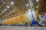
Integration and assembly
After each structure has received its TPS application, the major structures begin to be assembled. The first stage of this integration is known as the forward join, in which the forward skirt, LOx tank, and intertank are bolted together by their adapter flanges in Cell D at MAF Building 110. This process takes place with all structures vertically oriented.[25] These elements are not immediately joined to the liquid hydrogen tank, but instead undergo substantial outfitting work before being rotated back to a horizontal configuration.[25] After subsequent preparation of both the LH2 tank and forward join, these two structures are then integrated together, becoming a structure known as the "four-fifths".[26] Work at this stage includes TPS closeouts at the flange sections, which give the stage the appearance of having stripes.[20][27] At this point, work continues to prepare the four-fifths for attachment to the engine section. Tasks include installation of the systems tunnel, a cable routing visible on the exterior of the stage, the LOx feedlines, LH2 manifold, and completion of work inside the intertank, where avionics equipment is housed.[22]
-
 First mating of forward join, LOx tank and intertank, of CS-2
 -
 Completed forward join of CS-2
 -
 CS-2 "four-fifths" just after major mating
 -
 CS-2 with all major structures integrated
 -
 Completed CS-1

.jpg)
.jpg)
.jpg)

Revised integration procedure
Procedures for the final major join in the production of a core stage are different for the first two production items compared to subsequent ones. For core stages 1 and 2, the four-fifths were mated horizontally in the Michoud Assembly Facility. By contrast, subsequent stages will see the four-fifths transported to the Kennedy Space Center in Florida, where it will meet the engine section, both elements having been moved to High Bay 2 of the Vehicle Assembly Building. Boeing plans to have each part of the vehicle as complete as possible before integrating them, allowing the core stages to be finished with minimal work in the High Bay. Once completed, the stages are to be stored in the former Space Shuttle External Tank storage and checkout cells, awaiting stacking with the rest of an SLS vehicle.[14]
History
Origins
The core stage, as with the rest of the Space Launch System, has its roots in the NASA Authorization Act of 2010, which decreed that NASA build a heavy-lift launch vehicle capable of lifting 70 tonnes of cargo to Low Earth orbit by 2017. In response to this requirement, the Marshall Spaceflight Center (MSFC) began a series of studies intended to provide a basis on which NASA HQ would decide upon a suitable launch-vehicle architecture. These studies included an open competition between three teams – one investigating Space Shuttle-derived designs, another investigating large hydrocarbon-fueled booster rockets, and another studying modular vehicles on the basis of the Evolved Expendable Launch Vehicles.[28][29] Ultimately, the favored result of these studies was a Shuttle-derived architecture resembling the modern-day Space Launch System. However, this concept included a core stage derived from and identical in length to the Space Shuttle External Tank. It also possessed only three RS-25 engines, rather than four.[29] This proposal, however, was turned down by NASA administrator Charles Bolden, who requested a design could be evolved to one capable of lifting 130 metric tonnes to orbit.[30] By August 2011, External Tank production at MAF, contracted to Lockheed Martin, had ended, with workers laid off and tooling broken up.[31] Simultaneously, Boeing began unsolicited projects, based on tooling it had acquired for the by-then defunct Ares I rocket. Boeing had been selected to manufacture the upper stage of the Ares I, and the 2010 NASA Authorization Act instructed NASA to continue contracts signed for Ares I to the extent possible. In September 2011, a definitive design concept for the SLS core stage was presented. It was to be 8.4 meters in diameter, longer than the Space Shuttle external tank, and powered by four RS-25 engines, a configuration broadly similar to the core stage as built.[32]
The NASA Authorization Act of 2010 directed NASA to, where practicable, reuse Space Shuttle and Constellation program parts and contractors. To fulfill this, manufacture of the first two SLS core stages was initially award in 2012 under a modification (number 96) of the existing Ares Stages contract to The Boeing Company. The base contract had seen Boeing responsible for the delivery of the Ares I upper stage; the modification changed the requirement entirely to encompass the requirements for two core stages. This modification was an undefined action that did not specify the extent of the work Boeing was to complete.[33]
Design maturation
By December 2012, the SLS core stage passed its

In June 2014, the core stage passed its
In spring and summer of 2015, the Space Launch System as a whole went through its critical design review. During this period, the core stage began to be depicted unpainted, in the natural orange color of its thermal protection system. Before the critical design review, the stage had been shown as painted white and black in a scheme reminiscent of the Saturn V.[38]
Production troubles
Since 2014, Boeing had begun to experience a number of issues in establishing SLS production that caused significant delays to schedule. A number of fuel tubes which had been contaminated before delivery by the supplier resulted in the decision to reinspect all engine section tubing, which caused a delay of several months. The Vertical Assembly Center, a critical tool in the manufacture of the core stage's propellant tanks, was initially improperly installed, such that the tool was not able to properly lift stage components into position.[39] When the defect was discovered in September 2014, it became necessary to completely rebuild the VAC.[33] Later, welding issues encountered throughout 2016 would then cause more issues. During manufacture of the Weld Confidence Articles, which tested the joining technologies used in core stage manufacture, two issues were encountered: small voids were forming in the bonded material, and tiny cracks were forming in the welding "pin", the element of a friction-stir weld tool whose rotation, analogous to a drill bit, provides energy with which to join two surfaces. The latter issue caused pins to frequently break, which would require extraction, having lodged themselves within the aluminum substrate. Boeing teams elected to modify the pin design in order to reduce the frequency of pin breakage. However, when items were welded using the new, redesigned pins, they tended to randomly exhibit sections of low strength, which appeared in approximately one out of fifteen (6.7%) of test panels investigated after the deficiency was discovered. This issue was eventually resolved by reverting to the original pin design.[33][40] Further delays resulted in February 2017 from a tornado strike at Michoud Assembly Facility, which damaged buildings and delayed production of the first core stage.[33][41]
First launch campaign
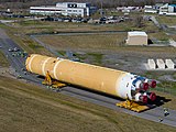
Through these issues, by the beginning of 2020, the first core stage was complete and ready to move to Stennis Space Center for the Green Run test campaign.[42] However, the stage was not to avoid further trouble. Workplace closures in response to the rapid spread of the COVID-19 pandemic cause months more of delays,[43] before the culminating test of the stage, the hot-fire, was prematurely ended due to several test parameters exceeding their designated limits, which were described as overly conservative.[44] A decision was subsequently made to repeat the test.[45] The Green Run campaign ended in May 2021, after a successful hot-fire test, and the first core stage was shipped to Kennedy Space Center and moved into the Vehicle Assembly Building, where it underwent further work ahead of integration as the core of the first SLS.[46]

Following a period of repair work on the core stage's thermal protection system to address damage taken during the Green Run campaign, CS-1 was rotated and stacked as the central element of the Artemis 1 Space Launch System.[47][48] Thereafter, it took part in the testing campaign of that vehicle, encountering issues related to the core stage's tail service mast umbilical connection, but successfully completing the sequence.[49] The first core stage flew a successful mission on November 16, 2022, splashing down in the Pacific Ocean.[50]
Beyond Artemis 1
As of October 2023[update] the second core stage, intended for its first crewed launch on Artemis 2, is currently being integrated in Building 103 at the Michoud Assembly Facility, with its engines fully installed.[51]
In December 2022, Boeing made the decision to disperse some core stage production work to several sites, adding the Space Station Processing Facility and Vehicle Assembly Building High Bay 2 to the CS production flow. The company stated that the change was made to increase production capacity for core stages, to reduce cost per unit, and to enable the storage of stages not immediately needed. Projections were made of cost reductions of up to $50 million per stage as a result of the new flow, and Boeing stated that the increased use could enable it to produce two core stages per year.[14]
Contract extension and reworking
The procurement of the core stage has been extended to allow for production of more than the originally ordered two stages, and a future contract award is expected to transfer operations of the Space Launch System and with it responsibility for procurement of the core stage away from NASA. In October 2019, NASA funded and authorised the beginining of production work of the third core stage, with a full contract option finalization in December 2022 allowing work to proceed at full scale towards the production of the fourth core stage and clarifying funding for both the third and fourth.[52] In July of that year, NASA also announced its intention to shift operations of the Space Launch System to Deep Space Transport LLC, a joint venture of core stage manufacturer Boeing and boosters supplier Northrop Grumman under the Exploration Production and Operations Contract. Deep Space Transport would be responsible for operating the SLS for NASA, and would also be permitted to market the rocket to other customers. The contract was not open to competition, as alternative bidders would have had to establish new production lines for the rocket's stages, including the core stage, for which an alternate production line was estimated to require up to 10 years to set up.[53]
List of stages
| Stage | Engine assignment[54] | Status | Flight date | Notes |
|---|---|---|---|---|
| STA | N/A | Structural elements only, testing complete.[55] | 5 segments were each tested separately, never joined together. Propellant tanks purposely burst as part of testing.[55] | |
| CS-1 | E2045, E2056, E2058, E2060 | Flown on Artemis 1. | November 16, 2022 | Used for "Green Run" testing campaign, undergoing 2 test firings at Stennis Space Center.[56] |
| CS-2 | E2047, E2059, E2062, E2063[†] | Major elements joined, engines installed. Undergoing integration work.[57] [58] | NET November 2024[59] | |
| CS-3 | E2048, E2054, E2057, E2061 | In manufacturing at Michoud Assembly Facility; engine section at Kennedy Space Center Space Station Processing Facility.[60] | NET December 2025[61] | First core stage with engine section integration planned to take place at Kennedy Space Center.[14] Uses LH2 tank originally intended for CS-1. |
| CS-4 | E2044, E2050, E2051, E2052 | In manufacturing.[16] | NET September 2028[62] | |
| CS-5 | Procurement of long-lead items.[16] | NET September 2029[63] | First core stage to be procured by Deep Space Transport instead of NASA.[64] First core stage to use Production Restart RS-25 engines.[65] | |
| CS-6 |
† E2062 and E2063 are new engines assembled from parts left over from the Space Shuttle Program, some already flown.[66]
References
- ^ a b c d e f Harbaugh, Jennifer (February 4, 2020). "Space Launch System Core Stage". NASA. Archived from the original on April 21, 2023. Retrieved August 17, 2023.
- ^ "NASA Artemis I Press Kit". NASA. Archived from the original on August 28, 2022. Retrieved August 17, 2023.
- ^ Boen, Brooke (June 6, 2013). "NASA Announces Design for New Deep Space Exploration System". NASA. Retrieved September 14, 2023.
- ^ a b c NASA's Space Launch System Reference Guide (PDF) (Report). August 1, 2022. Archived (PDF) from the original on August 19, 2023. Retrieved August 19, 2023.
- ^ Sloss, Philip (June 7, 2019). "SLS Core Stage MPS: more than just a fuel tank". NASASpaceFlight.com. Archived from the original on August 19, 2023. Retrieved August 19, 2023.
- ^ Sloss, Philip (August 9, 2019). "Boeing assembling structures for NASA's second SLS Core Stage". NASASpaceFlight.com. Archived from the original on August 10, 2019. Retrieved August 19, 2023.
- ^ Sloss, Philip (August 9, 2019). "Boeing assembling structures for NASA's second SLS Core Stage". NASASpaceFlight.com. Archived from the original on August 10, 2019. Retrieved August 19, 2023.
- ^ Mohon, Lee (September 2, 2022). "Engineers Chill Space Launch System Rocket Engines Before Launch". NASA. Archived from the original on January 29, 2023. Retrieved August 19, 2023.
- ^ Sloss, Philip (June 7, 2019). "SLS Core Stage MPS: more than just a fuel tank". NASASpaceFlight.com. Archived from the original on August 19, 2023. Retrieved August 19, 2023.
- ^ a b c d "SLS External Tank Reverts to Hard Alloy –". www.spacesafetymagazine.com. Archived from the original on August 17, 2023. Retrieved August 17, 2023.
- ^ a b Space Shuttle Historical Narrative (PDF) (Report). October 1, 2012. Archived (PDF) from the original on June 4, 2017. Retrieved August 19, 2023.
- ^ Harbaugh, Jennifer (July 7, 2021). "NASA's Michoud Assembly Facility". NASA. Archived from the original on May 12, 2023. Retrieved August 18, 2023.
- ^ a b Administrator, NASA Content (April 16, 2015). "Space Launch System: Tooling Up to Build the World's Largest Rocket". NASA. Archived from the original on May 25, 2023. Retrieved August 17, 2023.
- ^ a b c d e f g h Sloss, Philip (December 10, 2022). "Boeing expanding SLS Core Stage production to KSC to build Artemis inventory". NASASpaceFlight.com. Archived from the original on August 17, 2023. Retrieved August 17, 2023.
- ^ Admin, Futuramic (December 9, 2022). "NASA Moves Core Stage 3 Intertank". Futuramic. Archived from the original on August 17, 2023. Retrieved August 17, 2023.
- ^ a b c d e f g h Sloss, Philip (August 1, 2022). "SLS Stages in assembly at MAF for future NASA Artemis launches". NASASpaceFlight.com. Archived from the original on August 17, 2023. Retrieved August 17, 2023.
- ^ Bergin, Chris (May 8, 2017). "SLS Core Stage team recovering from consequences of weld pin change". NASASpaceFlight.com. Archived from the original on August 17, 2023. Retrieved August 17, 2023.
- ^ Harbaugh, Jennifer (February 20, 2018). "SLS Intertank". NASA. Archived from the original on August 17, 2023. Retrieved August 17, 2023.
- ^ "SLS Core Stage Production Continues for Rocket's First Flight". Space Daily. Archived from the original on August 17, 2023. Retrieved August 17, 2023.
- ^ a b c d e f g h Sloss, Philip (December 8, 2017). "Protecting SLS from Fire and Ice – TPS foam application proceeding at MAF". NASASpaceFlight.com. Archived from the original on August 17, 2023. Retrieved August 17, 2023.
- ^ a b c d Sloss, Philip (July 19, 2021). "Boeing working on multiple Cores, first EUS hardware for Artemis missions 2–4". NASASpaceFlight.com. Archived from the original on August 12, 2021. Retrieved August 17, 2023.
- ^ a b Sloss, Philip (July 25, 2022). "Boeing aiming to deliver second SLS Core Stage to NASA in March". NASASpaceFlight.com. Archived from the original on August 31, 2022. Retrieved August 17, 2023.
- ^ a b c Harbaugh, Jennifer (June 20, 2018). "Foam and Cork Insulation Protects Deep Space Rocket from Fire and Ice". NASA. Archived from the original on April 22, 2023. Retrieved August 17, 2023.
- ^ a b Sloss, Philip (May 20, 2021). "SLS Core Stage thermal protection system refurbishment in work at Kennedy for Artemis 1 – Page 2 of 2". NASASpaceFlight.com. Archived from the original on May 26, 2021. Retrieved August 17, 2023.
- ^ a b Sloss, Philip (May 24, 2021). "NASA and Boeing working on optimizing SLS stage production at MAF". NASASpaceFlight.com. Archived from the original on August 17, 2023. Retrieved August 17, 2023.
- ^ Sloss, Philip (March 12, 2021). "NASA, Boeing approaching first major join of second SLS Core Stage – Page 2 of 2". NASASpaceFlight.com. Archived from the original on August 17, 2023. Retrieved August 17, 2023.
- ^ Sloss, Philip (March 12, 2021). "NASA, Boeing approaching first major join of second SLS Core Stage". NASASpaceFlight.com. Archived from the original on August 17, 2023. Retrieved August 17, 2023.
- ^ Bergin, Chris (December 11, 2010). "HEFT: Space Launch System HLV design decision likely by April, 2011". NASASpaceFlight.com. Archived from the original on August 17, 2023. Retrieved August 17, 2023.
- ^ a b Bergin, Chris (April 25, 2011). "SLS planning focuses on dual phase approach opening with SD HLV". NASASpaceFlight.com. Archived from the original on June 29, 2019. Retrieved August 17, 2023.
- ^ Bergin, Chris (June 6, 2011). "SLS configuration nears decision point – Two-phase approach rejected". NASASpaceFlight.com. Archived from the original on August 17, 2023. Retrieved August 17, 2023.
- ^ Bergin, Chris (August 27, 2011). "Boeing complete SLS Pathfinder Tank as MAF ET operations end". NASASpaceFlight.com. Archived from the original on August 17, 2023. Retrieved August 17, 2023.
- ^ Bergin, Chris (September 15, 2011). "SLS finally announced by NASA – Forward path taking shape". NASASpaceFlight.com. Archived from the original on March 22, 2023. Retrieved August 17, 2023.
- ^ a b c d e NASA's Management of the Space Launch System Stages Contract (PDF) (Report). October 8, 2018. Archived (PDF) from the original on October 10, 2018. Retrieved August 17, 2023.
- ^ Cowing, Keith (December 21, 2012). "Space Launch System Core Stage Passes PDR". SpaceRef. Archived from the original on August 31, 2023. Retrieved August 17, 2023.
- ^ Bergin, Chris (February 18, 2013). "SLS takes on new buckling standards, drops Super Light alloy". NASASpaceFlight.com. Retrieved September 14, 2023.
- ^ Bergin, Chris (June 22, 2013). "SLS: MAF receiving extraordinary machinery for the exploration rocket". NASASpaceFlight.com. Archived from the original on August 17, 2023. Retrieved August 17, 2023.
- ^ "Space Launch System passes Critical Design Review for the core stage". SpaceFlight Insider. July 3, 2014. Archived from the original on August 31, 2023. Retrieved August 17, 2023.
- ^ Northon, Karen (October 22, 2015). "NASA Completes Critical Design Review for Space Launch System". NASA. Archived from the original on August 31, 2023. Retrieved August 17, 2023.
- ^ Leone, Dan (March 10, 2015). "Boeing Still Tinkering with Giant Welder for SLS Stages". SpaceNews. Retrieved September 14, 2023.
- ^ Bergin, Chris (May 8, 2017). "SLS Core Stage team recovering from consequences of weld pin change". NASASpaceFlight.com. Archived from the original on August 17, 2023. Retrieved August 17, 2023.
- ^ Mohon, Lee (February 13, 2017). "February 13, 2017: NASA Status Update on Tornado Recovery at MAF". NASA. Archived from the original on August 17, 2023. Retrieved August 17, 2023.
- ^ Sloss, Philip (January 25, 2020). "SLS Core Stage in Stennis B-2 Stand to start Green Run campaign". NASASpaceFlight.com. Archived from the original on August 7, 2020. Retrieved August 17, 2023.
- ^ Bergin, Chris (May 15, 2020). "Stennis returning as battle to protect SLS maiden launch in 2021 restarts". NASASpaceFlight.com. Archived from the original on August 17, 2023. Retrieved August 17, 2023.
- ^ Sloss, Philip (January 30, 2021). "NASA decides to redo SLS Green Run Static Fire". NASASpaceFlight.com. Archived from the original on August 17, 2023. Retrieved August 17, 2023.
- ^ "Hot fire test of NASA's SLS Rocket ends prematurely, placing 2021 launch date into question". SpaceFlight Insider. January 17, 2021. Archived from the original on August 17, 2023. Retrieved August 17, 2023.
- ^ Sempsrott, Danielle (April 28, 2021). "Barging In: Artemis I Core Stage Arrives at Kennedy". NASA. Retrieved August 17, 2023.
- ^ Sloss, Philip (June 11, 2021). "EGS starts Artemis 1 SLS Core Stage lift". NASASpaceFlight.com. Archived from the original on April 23, 2023. Retrieved August 18, 2023.
- ^ "NASA completes stacking SLS rocket for first Artemis moon mission". collectSPACE.com. Archived from the original on April 20, 2023. Retrieved August 18, 2023.
- ^ Beil, Adrian (July 2, 2022). "SLS rolled back to VAB for final launch preparations". NASASpaceFlight.com. Archived from the original on July 3, 2022. Retrieved August 18, 2023.
- ^ "NASA's Artemis 1 Space Launch System Moon rocket finally flies!". SpaceFlight Insider. November 16, 2022. Archived from the original on August 18, 2023. Retrieved August 18, 2023.
- ^ Clark, Stephen (September 29, 2023). "Rocket Report: Iran launches satellite; Artemis II boosters get train ride". Ars Technica. Retrieved October 2, 2023.
- ^ Bardan, Roxana (December 9, 2022). "NASA Commits to Future Artemis Moon Rocket Production". NASA. Archived from the original on August 20, 2023. Retrieved August 20, 2023.
- ^ Foust, Jeff (July 27, 2022). "NASA prepares to award SLS launch services contract to Boeing-Northrop joint venture". SpaceNews. Archived from the original on August 31, 2023. Retrieved August 20, 2023.
- ^ "RS-25 engine assignments". The Planetary Society. Archived from the original on August 17, 2023. Retrieved August 17, 2023.
- ^ a b Harbaugh, Jennifer (June 25, 2020). "NASA Completes Artemis Space Launch System Structural Testing Campaign". NASA. Archived from the original on August 31, 2023. Retrieved August 18, 2023.
- ^ Brown, David W.; Chang, Kenneth (March 18, 2021). "8 Minutes of Fire: NASA's 2nd Test of Giant New Moon Rocket Is a Success (Published 2021)". The New York Times. Archived from the original on August 18, 2023. Retrieved August 18, 2023.
- ^ "Boeing: Boeing – Boeing's core stage for 2nd Artemis mission nears completion". www.boeing.com. Archived from the original on August 17, 2023. Retrieved August 17, 2023.
- ^ "All Engines Added to NASA's Artemis II Moon Rocket Core Stage – Artemis". blogs.nasa.gov. September 25, 2023. Retrieved September 26, 2023.
- ^ "NASA's Artemis 2 mission around Moon set for November 2024". Phys.org. Agence France-Presse. March 7, 2023. Archived from the original on March 7, 2023. Retrieved March 8, 2023.
- ^ Admin, Futuramic (December 18, 2022). "Artemis III Core Stage Segment Move to Work Stand". Futuramic. Archived from the original on August 18, 2023. Retrieved August 18, 2023.
- ^ Foust, Jeff (August 9, 2023). "NASA weighs changes to Artemis 3 if key elements are delayed". SpaceNews. Archived from the original on August 31, 2023. Retrieved August 19, 2023.
- ^ "NASA concerned SpaceX's Starship schedule could delay moon landing – Spaceflight Now". Archived from the original on August 19, 2023. Retrieved August 19, 2023.
- ^ "NASA announced Artemis 2 moon astronauts Monday". earthsky.org. April 4, 2023. Archived from the original on August 19, 2023. Retrieved August 19, 2023.
- ^ Foust, Jeff (July 27, 2022). "NASA prepares to award SLS launch services contract to Boeing-Northrop joint venture". SpaceNews. Archived from the original on August 31, 2023. Retrieved August 18, 2023.
- ^ Ridgeway, Beth (March 28, 2023). "NASA Rocket Engines Re-engineered for Next Era of Exploration". NASA. Archived from the original on June 5, 2023. Retrieved August 18, 2023.
- ^ Mohon, Lee (September 27, 2022). "Artemis II Rocket Engines Arrive at NASA's Michoud Assembly Facility". NASA. Archived from the original on April 10, 2023. Retrieved August 17, 2023.