
Serial port

A serial port is a serial communication interface through which information transfers in or out sequentially one bit at a time.[1] This is in contrast to a parallel port, which communicates multiple bits simultaneously in parallel. Throughout most of the history of personal computers, data has been transferred through serial ports to devices such as modems, terminals, various peripherals, and directly between computers.
While interfaces such as
Modern consumer personal computers (PCs) have largely replaced serial ports with higher-speed standards, primarily USB. However, serial ports are still frequently used in applications demanding simple, low-speed interfaces, such as industrial automation systems, scientific instruments, point of sale systems and some industrial and consumer products.
Hardware
This section needs additional citations for verification. (November 2021) |
Modern devices use an
Very low-cost systems, such as some early
Before
-
 AnIBM PC serial card with a 25-pin connector (obsolete 8-bit ISAcard)
 -
 A PCI Express ×1 card with one serial port
 -
 A four-port serial (RS-232) PCI Express ×1octopus cablethat breaks the card's DC-37 connector into four standard DE-9 connectors
 -
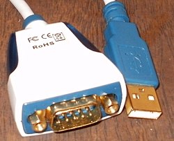 A converter from USB to an RS-232 compatible serial port—more than a physical transition, it requires a driver in the host system software and a built-in processor to emulate the functions of theIBM XTcompatible serial port hardware.
 -
 UART to USB adapter


DTE and DCE
The individual signals on a serial port are unidirectional and when connecting two devices, the outputs of one device must be connected to the inputs of the other. Devices are divided into two categories: data terminal equipment (DTE) and data circuit-terminating equipment (DCE). A line that is an output on a DTE device is an input on a DCE device and vice versa, so a DCE device can be connected to a DTE device with a straight wired cable, in which each pin on one end goes to the same numbered pin on the other end.
Conventionally, computers and terminals are DTE, while peripherals such as modems are DCE. If it is necessary to connect two DTE (or DCE) devices together, a cable with reversed TX and RX lines, known as a cross-over, roll-over or null modem cable must be used.
Gender
Generally, serial port connectors are gendered, only allowing connectors to mate with a connector of the opposite gender. With D-subminiature connectors, the male connectors have protruding pins and female connectors have corresponding round sockets.[2] Either type of connector can be mounted on equipment or a panel; or terminate a cable.
Connectors mounted on DTE are likely to be male, and those mounted on DCE are likely to be female (with the cable connectors being the opposite). However, this is far from universal; for instance, most serial printers have a female DB25 connector, but they are DTEs.[3] In this circumstance, the appropriately gendered connectors on the cable or a gender changer can be used to correct the mismatch.
Connectors
The only connector specified in the original RS-232 standard was the 25-pin D-subminiature, however, many other connectors have been used to save money or save on physical space, among other reasons. In particular, since many devices do not use all of the 20 signals that are defined by the standard, connectors with fewer pins are often used. While specific examples follow, countless other connectors have been used for RS-232 connections.
The 9-pin
Some miniaturized electronics, particularly graphing calculators[5] and hand-held amateur and two-way radio equipment,[6] have serial ports using a phone connector, usually the smaller 2.5 or 3.5 mm connectors and the most basic 3-wire interface—transmit, receive and ground.
Many models of
Another common connector is a 10 × 2 pin header common on motherboards and add-in cards which is usually converted via a ribbon cable to the more standard 9-pin DE-9 connector (and frequently mounted on a free slot plate or other part of the housing).[10]
-
 A Cisco rollover cable using the 8P8C Yost standard.
 -
 Pair of femaleMini DIN-8 connectors used for RS-422 serial ports on a Macintosh LCcomputer.
 -
 Pin numbering looking into a
male DE-9 connector. -
 Pin numbering looking into a
female DE-9 connector.


Pinouts
The following table lists commonly used RS-232 signals and pin assignments:[11]
| Signal | Direction | Connector pin | |||||||||||||
|---|---|---|---|---|---|---|---|---|---|---|---|---|---|---|---|
| Name | V.24 circuit |
Abbreviation | DTE | DCE | DB-25 |
TIA-574 ) |
MMJ | 8P8C ("RJ45") |
10P10C ("RJ50")
| ||||||
| EIA/TIA-561 | Yost (DTE)[12] | Yost (DCE)[12] | Cyclades | Digi (ALTPIN option) | National Instruments[9] | Cyclades | Digi | ||||||||
| Transmitted Data | 103 | TxD | Out | In | 2 | 3 | 2 | 6 | 6 | 3 | 3 | 4 | 8 | 4 | 5 |
| Received Data | 104 | RxD | In | Out | 3 | 2 | 5 | 5 | 3 | 6 | 6 | 5 | 9 | 7 | 6 |
| Data Terminal Ready | 108/2 | DTR | Out | In | 20 | 4 | 1 | 3 | 7 | 2 | 2 | 8 | 7 | 3 | 9 |
| Data Carrier Detect | 109 | DCD | In | Out | 8 | 1 | — | 2 | 2 | 7 | 7 | 1 | 10 | 8 | 10 |
| Data Set Ready | 107 | DSR | In | Out | 6 | 6 | 6 | 1 | — | 8 | — | 5 | 9 | 2 | |
| Ring Indicator | 125 | RI | In | Out | 22 | 9 | — | — | — | — | — | 2 | 10 | 1 | |
| Request To Send | 105 | RTS | Out | In | 4 | 7 | — | 8 | 8 | 1 | 1 | 2 | 4 | 2 | 3 |
| Clear To Send | 106 | CTS | In | Out | 5 | 8 | — | 7 | 1 | 8 | 5 | 7 | 3 | 6 | 8 |
| Signal Ground | 102 | G | Common | 7 | 5 | 3, 4 | 4 | 4, 5 | 4, 5 | 4 | 6 | 6 | 5 | 7 | |
| Protective Ground | 101 | PG | Common | 1 | — | — | — | — | — | — | 3 | — | 1 | 4 | |
Signal Ground is a common return for the other connections; it appears on two pins in the Yost standard but is the same signal. The DB-25 connector includes a second Protective Ground on pin 1, which is intended to be connected by each device to its own frame ground or similar. Connecting Protective Ground to Signal Ground is a common practice but not recommended.
Note that EIA/TIA 561 combines DSR and RI,[13][14] and the Yost standard combines DSR and DCD.
Hardware abstraction
Operating systems usually create symbolic names for the serial ports of a computer, rather than requiring programs to refer to them by hardware address.
The
Common applications for serial ports
This list includes some of the more common devices that are connected to the serial port on a PC. Some of these such as modems and serial mice are falling into disuse while others are readily available. Serial ports are very common on most types of microcontroller, where they can be used to communicate with a PC or other serial devices.
- Dial-up modems
- Configuration and management of load balancers
- GPS receivers (typically NMEA 0183at 4,800 bit/s)
- Bar code scanners and other point of saledevices
- LCDtext displays
- Satellite phones, low-speed satellite modems and other satellite-based transceiver devices
- Flat-panel displays to control screen functions by external computer, other AV components or remotes
- Test and measuring equipment such as digital multimeters and weighing systems
- Updating firmware on various consumer devices
- CNC controllers
- Uninterruptible power supply management and status reporting
- Stenography or Stenotype machines
- Software debuggers that run on a second computer
- Console or debugger interface to microprocessor development or evaluation boards
- Industrial field buses
- Printers
- teletype
- Networking (Macintosh AppleTalk using RS-422 at 230.4 kbit/s)
- Serial mouse
Since the control signals for a serial port can be driven by any digital signal, some applications used the control lines of a serial port to monitor external devices, without exchanging serial data. A common commercial application of this principle was for some models of uninterruptible power supply which used the control lines to signal loss of power, low battery, and other status information. At least some Morse code training software used a code key connected to the serial port to simulate actual code use; the status bits of the serial port could be sampled very rapidly and at predictable times, making it possible for the software to decipher Morse code.
Serial computer mice may draw their operating power from the received data or control signals.[16][17]
Settings
| Bit rate (bit/s) | Time per bit (μs) | Common applications | |
|---|---|---|---|
| 75 | 13333.3 | Yes | |
| 110 | 9090.9 | Yes | Bell 101 modem
|
| 134.5 | 7434.9 | Yes | IBM 2741 terminal |
| 150 | 6666.6 | Yes | |
| 300 | 3333.3 | Yes | V.21 modem
|
| 600 | 1666.7 | Yes | |
| 1,200 | 833.3 | Yes | V.22 modem
|
| 1,800 | 555.6 | Yes | |
| 2,400 | 416.7 | Yes | V.22bis modem
|
| 4,800 | 208.3 | Yes | V.27ter modem
|
| 7,200 | 138.9 | Yes | |
| 9,600 | 104.2 | Yes | V.32 modem
|
| 14,400 | 69.4 | Yes | V.32bis modem
|
| 19,200 | 52.1 | Yes | |
| 31,250 | 32 | No | MIDI port |
| 38,400 | 26.0 | Yes | |
| 56,000 | 17.9 | Yes | V.92 modem
|
| 57,600 | 17.4 | Yes | V.42bis compression
|
| 76,800 | 13.0 | No | |
| 115,200 | 8.68 | Yes | V.44 compression
|
| 125,000 | 8.00 | No | ISO 11898-3 CAN bus |
| 128,000 | 7.81 | Yes | Basic Rate Interface ISDN terminal adapter |
| 230,400 | 4.34 | No | |
| 250,000 | 4.0 | No | DMX512, stage lighting and effects network |
| 256,000 | 3.91 | Yes |
Serial standards provide for many different operating speeds as well as adjustments to the protocol to account for different operating conditions. The most well-known options are speed, number of data bits per character, parity, and number of stop bits per character.
In modern serial ports using a UART integrated circuit, all these settings can be software-controlled. Hardware from the 1980s and earlier may require setting switches or jumpers on a circuit board.
The configuration for serial ports designed to be connected to a PC has become a de facto standard, usually stated as 9600/8-N-1.
Speed
Serial ports use two-level (binary) signaling, so the data rate in bits per second is equal to the symbol rate in baud. The total speed includes bits for framing (stop bits, parity, etc.) and so the effective data rate is lower than the bit transmission rate. For example, with 8-N-1 character framing, only 80% of the bits are available for data; for every eight bits of data, two more framing bits are sent.
A standard series of rates is based on multiples of the rates for electromechanical teleprinters; some serial ports allow many arbitrary rates to be selected, but the speeds on both sides of the connection must match for data to be received correctly. Bit rates commonly supported include 75, 110, 300, 1200, 2400, 4800, 9600, 19200, 38400, 57600 and 115200 bit/s.[19] Many of these standard modem bit rates are multiples of either 1.2 kbit/s (e.g., 19200, 38400, 76800) or 0.9 kbit/s (e.g., 57600, 115200).[22] Crystal oscillators with a frequency of 1.843200 MHz are sold specifically for this purpose. This is 16 times the fastest bit rate, and the serial port circuit can easily divide this down to lower frequencies as required.
The capability to set a bit rate does not imply that a working connection will result. Not all bit rates are possible with all serial ports. Some special-purpose protocols such as MIDI for musical instrument control, use serial data rates other than the teleprinter standards. Some serial port implementations can automatically choose a bit rate by observing what a connected device is sending and synchronizing to it.
Data bits
The number of data bits in each character can be 5 (for Baudot code), 6 (rarely used), 7 (for true ASCII), 8 (for most kinds of data, as this size matches the size of a byte), or 9 (rarely used). 8 data bits are almost universally used in newer applications. 5 or 7 bits generally only make sense with older equipment such as teleprinters.
Most serial communications designs send the data bits within each byte
Parity
Parity is a method of detecting errors in transmission. When parity is used with a serial port, an extra data bit is sent with each data character, arranged so that the number of 1 bits in each character, including the parity bit, is always odd or always even. If a byte is received with the wrong number of 1s, then it must have been corrupted. Correct parity does not necessarily indicate absence of corruption as a corrupted transmission with an even number of errors will pass the parity check. A single parity bit does not allow implementation of
The parity bit in each character can be set to one of the following:
- None (N) means that no parity bit is sent and the transmission is shortened.
- Odd (O) means that the parity bit is set so that the number of 1 bits is odd.
- Even (E) means that the parity bit is set so that the number of 1 bits is even.
- Mark (M) parity means that the parity bit is always set to the mark signal condition (1 bit value).
- Space (S) parity always sends the parity bit in the space signal condition (0 bit value).
Aside from uncommon applications that use the last bit (usually the 9th) for some form of addressing or special signaling, mark or space parity is uncommon, as it adds no error detection information.
Odd parity is more useful than even parity since it ensures that at least one state transition occurs in each character, which makes it more reliable at detecting errors like those that could be caused by serial port speed mismatches. The most common parity setting, however, is none, with error detection handled by a communication protocol.
To allow detection of messages damaged by
Stop bits
Stop bits sent at the end of every character allow the receiving signal hardware to detect the end of a character and to resynchronize with the character stream. Electronic devices usually use one stop bit. If slow electromechanical teleprinters are used, one-and-one-half or two stop bits may be required.
Conventional notation

The data/parity/stop (D/P/S) conventional notation specifies the framing of a serial connection. The most common configuration for the personal computing devices is 8-N-1 (also spelled as 8N1, 8-None-1[23]), in which there is one start bit, eight ("8") data bits, no ("N") parity bit, and one ("1") stop bit.[24] In this notation, the parity bit is not included into the count of the data bits. For example, 7/E/1 (7E1) means that an even parity bit is added to the 7 data bits for a total of 8 bits between the start and stop bits.
The abbreviation is usually given together with the line speed in
Flow control
Flow control is used in circumstances where a transmitter might be able to send data faster than the receiver is able to process it. To cope with this, serial lines often incorporate a handshaking method. There are hardware and software handshaking methods.
Hardware handshaking is done with extra signals, often the RS-232 RTS/CTS or DTR/DSR signal circuits. RTS and CTS are used to control data flow, signaling, for instance, when a buffer is almost full. Per the RS-232 standard and its successors, DTR and DSR are used to signal that equipment is present and powered up so are usually asserted at all times. However, non-standard implementations exist, for example, printers that use DTR as flow control.
Software handshaking is done for example with
The advantage of hardware handshaking is that it can be extremely fast, it works independently of imposed meaning such as ASCII on the transferred data and it is stateless. Its disadvantage is that it requires more hardware and cabling, and both ends of the connection must support the hardware handshaking protocol used.
The advantage of software handshaking is that it can be done with absent or incompatible hardware handshaking circuits and cabling. The disadvantage, common to all in-band control signaling, is that it introduces complexities in ensuring that control messages get through even when data messages are blocked, and data can never be mistaken for control signals. The former is normally dealt with by the operating system or device driver; the latter normally by ensuring that control codes are
If no handshaking is employed, an overrun receiver might simply fail to receive data from the transmitter. Approaches for preventing this include reducing the speed of the connection so that the receiver can always keep up, increasing the size of buffers so it can keep up averaged over a longer time, using delays after time-consuming operations (e.g. in termcap) or employing a mechanism to resend data which has not been received correctly (e.g. TCP).
See also
- List of Bluetooth profiles § Serial Port Profile (SPP)
- Serial over LAN – A mechanism that allows the serial port of a managed system to be redirected over IP
- Teleprinter – Device that motivated serial port development
- Virtual COM port – A software representation of a serial port
References
- ^ Beal, Vangie (September 1996). "Serial Port Definition & Meaning". Webopedia. Retrieved 2021-03-08.
- ^ "Serial Cable Connection Guide". CISCO. 2006-08-01. Retrieved 2016-01-31.
- ^ "RS232 - DTE and DCE connectors". Lantronix. 2006-03-29. Archived from the original on 2015-12-14. Retrieved 2016-01-31.
- ^ "IBM PC AT Serial/Parallel Adapter" (PDF). Archived from the original (PDF) on 2020-02-24.
- ^ "TI-73...92+/V200 TI Link Guide". merthsoft.com. Retrieved 2020-08-14.
- ^ "Technical Section". Miklor.com. Retrieved 2020-08-14.
- ^ "Cabling Guide for Console and AUX Ports". Cisco. Retrieved 2020-08-14.
- ^ "Classic Mac Ports". WhiteFiles.org. Retrieved 2020-08-14.
- ^ a b "Serial Quick Reference Guide" (PDF). NI.com. National Instruments. July 2013. Retrieved 2021-06-18.
- ^ Intel Server Board S5000PAL/S5000XAL Technical Product Specification (PDF). p. 38.
- ^ Ögren, Joakim. "Serial (PC 9)". Archived from the original on 2010-08-11. Retrieved 2010-07-07.
- ^ a b "Yost Serial Device Wiring Standard". Archived from the original on 2020-06-17. Retrieved 2020-05-10.
- ^ "Hardware Book RS-232D".
- ^ "RS-232D EIA/TIA-561 RJ45 Pinout".
- ^ Stephen Byron Cooper. "What Is a Com1 Port?". Techwalla. Retrieved 2021-09-30.
- ^ Chan, Alvin (1990). "AN-681 PC Mouse Implementation Using COP800" (PDF). National Semiconductor. Retrieved 29 July 2023.
- ^ "AN519 Implementing a Simple Serial Mouse Controller" (PDF). Microchip Technology Inc. 1997. Retrieved 29 July 2023.
- ^ "_SERIAL_COMMPROP (ntddser.h) - Windows drivers {{|}} Microsoft Learn". Windows Hardware Developer. Microsoft. 2022-09-01. Retrieved 2025-02-08.
- ^ a b "DCB (winbase.h) - Windows apps {{|}} Microsoft Learn". Windows App Development. Microsoft. 2021-04-01. Retrieved 2025-02-08.
- ^ "MultiModem ZBA" (PDF). Multi-Tech Systems, Inc. January 2019. Archived from the original (PDF) on March 3, 2019. Retrieved September 26, 2019.
- ^ "Courier 56K Business Modem: User Guide: Controlling Data Rates". USRobotics. 2007. Archived from the original on August 4, 2017. Retrieved September 26, 2019.
- ^ "SX1272/73 - 860 MHz to 1020 MHz Low Power Long Range Transceiver Datasheet" (PDF). Semtech. January 2019.
- ^ a b "What does 8-N-1 mean?". modemhelp.net. Retrieved 2013-12-25.
- ^ "Definition of N-8-1". PCMAG.
Further reading
- Serial Port Complete: COM Ports, USB Virtual COM Ports, and Ports for Embedded Systems; 2nd Edition; Jan Axelson; Lakeview Research; 380 pages; 2007; ISBN 978-1-931-44806-2.
External links
 Media related to Serial port at Wikimedia Commons
- RS-232 and other serial port pinouts list