
Insulator (electricity)
| Articles about |
| Electromagnetism |
|---|
 |


An electrical insulator is a material in which
A perfect insulator does not exist because even insulators contain small numbers of mobile charges (
Insulators are used in electrical equipment to support and separate electrical conductors without allowing current through themselves. An insulating material used in bulk to wrap electrical cables or other equipment is called insulation. The term insulator is also used more specifically to refer to insulating supports used to attach electric power distribution or transmission lines to utility poles and transmission towers. They support the weight of the suspended wires without allowing the current to flow through the tower to ground.
Physics of conduction in solids
Electrical insulation is the absence of
Most insulators have a large band gap. This occurs because the "valence" band containing the highest energy electrons is full, and a large energy gap separates this band from the next band above it. There is always some voltage (called the breakdown voltage) that gives electrons enough energy to be excited into this band. Once this voltage is exceeded, electrical breakdown occurs, and the material ceases being an insulator, passing charge. This is usually accompanied by physical or chemical changes that permanently degrade the material and its insulating properties.
When the electric field applied across an insulating substance exceeds in any location the threshold breakdown field for that substance, the insulator suddenly becomes a conductor, causing a large increase in current, an electric arc through the substance. Electrical breakdown occurs when the electric field in the material is strong enough to accelerate free charge carriers (electrons and ions, which are always present at low concentrations) to a high enough velocity to knock electrons from atoms when they strike them, ionizing the atoms. These freed electrons and ions are in turn accelerated and strike other atoms, creating more charge carriers, in a chain reaction. Rapidly the insulator becomes filled with mobile charge carriers, and its resistance drops to a low level. In a solid, the breakdown voltage is proportional to the band gap energy. When corona discharge occurs, the air in a region around a high-voltage conductor can break down and ionise without a catastrophic increase in current. However, if the region of air breakdown extends to another conductor at a different voltage it creates a conductive path between them, and a large current flows through the air, creating an electric arc. Even a vacuum can suffer a sort of breakdown, but in this case the breakdown or vacuum arc involves charges ejected from the surface of metal electrodes rather than produced by the vacuum itself.
In addition, all insulators become conductors at very high temperatures as the thermal energy of the valence electrons is sufficient to put them in the conduction band.[1][2]
In certain capacitors, shorts between electrodes formed due to dielectric breakdown can disappear when the applied electric field is reduced.[3][4][5][relevant?]
Uses
A flexible coating of an insulator is often applied to electric wire and cable; this assembly is called insulated wire. Wires sometimes don't use an insulating coating, just air, when a solid (e.g. plastic) coating may be impractical. Wires that touch each other produce cross connections,
Most insulated wire and cable products have maximum ratings for voltage and conductor temperature. The product may not have an ampacity (current-carrying capacity) rating, since this is dependent on the surrounding environment (e.g. ambient temperature).
In electronic systems,
In microelectronic components such as transistors and ICs, the silicon material is normally a conductor because of doping, but it can easily be selectively transformed into a good insulator by the application of heat and oxygen. Oxidised silicon is quartz, i.e. silicon dioxide, the primary component of glass.
In
Insulation in electrical apparatus

The most important insulation material is air. A variety of solid, liquid, and
In older apparatus made up to the early 1970s, boards made of compressed asbestos may be found; while this is an adequate insulator at power frequencies, handling or repairs to asbestos material can release dangerous fibers into the air and must be carried out cautiously. Wire insulated with felted asbestos was used in high-temperature and rugged applications from the 1920s. Wire of this type was sold by General Electric under the trade name "Deltabeston."[6]
Live-front switchboards up to the early part of the 20th century were made of slate or marble. Some high voltage equipment is designed to operate within a high pressure
Electrical wires may be insulated with
Flexible insulating materials such as PVC (polyvinyl chloride) are used to insulate the circuit and prevent human contact with a 'live' wire – one having voltage of 600 volts or less. Alternative materials are likely to become increasingly used due to EU safety and environmental legislation making PVC less economic.
In electrical apparatus such as motors, generators, and transformers, various insulation systems are used, classified by their maximum recommended working temperature to achieve acceptable operating life. Materials range from upgraded types of paper to inorganic compounds.
Class I and Class II insulation
All portable or hand-held electrical devices are insulated to protect their user from harmful shock.
Class I insulation requires that the metal body and other exposed metal parts of the device be connected to earth via a grounding wire that is
Class II insulation means that the device is double insulated. This is used on some appliances such as electric shavers, hair dryers and portable power tools. Double insulation requires that the devices have both basic and supplementary insulation, each of which is sufficient to prevent
It has been suggested that this article should be electrical insulator. (discuss ) (June 2021) |
Telegraph and power transmission insulators
Conductors for overhead high-voltage electric power transmission are bare, and are insulated by the surrounding air. Conductors for lower voltages in distribution may have some insulation but are often bare as well. Insulating supports are required at the points where they are supported by utility poles or transmission towers. Insulators are also required where wire enters buildings or electrical devices, such as transformers or circuit breakers, for insulation from the case. Often these are bushings, which are hollow insulators with the conductor inside them.
Materials
Insulators used for high-voltage power transmission are made from
Some electric utilities use polymer
-
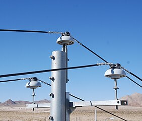 Power lines supported by ceramic pin-type insulators in California, USA
 -
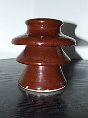 10 kV ceramic insulator, showing sheds


Design

The electrical breakdown of an insulator due to excessive voltage can occur in one of two ways:
- A puncture arc is a breakdown and conduction of the material of the insulator, causing an electric arc through the interior of the insulator. The heat resulting from the arc usually damages the insulator irreparably. Puncture voltage is the voltage across the insulator (when installed in its normal manner) that causes a puncture arc.
- A flashover arc is a breakdown and conduction of the air around or along the surface of the insulator, causing an arc along the outside of the insulator. Insulators are usually designed to withstand flashover without damage. Flashover voltage is the voltage that causes a flash-over arc.
Most high voltage insulators are designed with a lower flashover voltage than puncture voltage, so they flash over before they puncture, to avoid damage.
Dirt, pollution, salt, and particularly water on the surface of a high voltage insulator can create a conductive path across it, causing leakage currents and flashovers. The flashover voltage can be reduced by more than 50% when the insulator is wet. High voltage insulators for outdoor use are shaped to maximise the length of the leakage path along the surface from one end to the other, called the creepage length, to minimise these leakage currents.[11] To accomplish this the surface is moulded into a series of corrugations or concentric disc shapes. These usually include one or more sheds; downward facing cup-shaped surfaces that act as umbrellas to ensure that the part of the surface leakage path under the 'cup' stays dry in wet weather. Minimum creepage distances are 20–25 mm/kV, but must be increased in high pollution or airborne sea-salt areas.
Types

Insulators are characterized in several common classes:
- annealedwire of the same material as the conductor. Pin-type insulators are used for transmission and distribution of communication signals, and electric power at voltages up to 33 kV. Insulators made for operating voltages between 33 kV and 69 kV tend to be bulky and have become uneconomical.
- Post insulator - A type of insulator in the 1930s that is more compact than traditional pin-type insulators and which has rapidly replaced many pin-type insulators on lines up to 69 kV and in some configurations, can be made for operation at up to 115 kV.
- Suspension insulator - For voltages greater than 33 kV, it is a usual practice to use suspension type insulators, consisting of a number of glass or porcelain discs connected in series by metal links in the form of a string. The conductor is suspended at the bottom end of this string while the top end is secured to the cross-arm of the tower. The number of disc units used depends on the voltage.
- crossarmin a horizontal direction. When the tension load in lines is exceedingly high, such as at long river spans, two or more strings are used in parallel.
- Shackle insulator - In early days, the shackle insulators were used as strain insulators. But nowaday, they are frequently used for low voltage distribution lines. Such insulators can be used either in a horizontal position or in a vertical position. They can be directly fixed to the pole with a bolt or to the cross arm.
- Bushing - enables one or several conductors to pass through a partition such as a wall or a tank, and insulates the conductors from it.[12]
- Line post insulator
- Station post insulator
- Cut-out
Sheath insulator

An insulator that protects a full length of bottom-contact third rail.
This section needs expansion. You can help by adding to it. (April 2021) |
Suspension insulators
| Line voltage (kV) |
Discs |
|---|---|
| 34.5 | 3 |
| 69 | 4 |
| 115 | 6 |
| 138 | 8 |
| 161 | 11 |
| 230 | 14 |
| 287 | 15 |
| 345 | 18 |
| 360 | 23 |
| 400 | 24 |
| 500 | 34 |
| 600 | 44 |
| 750 | 59 |
| 765 | 60 |
Pin-type insulators are unsuitable for voltages greater than about 69 kV line-to-line. Higher voltage
Each unit is constructed of a ceramic or glass disc with a metal cap and pin cemented to opposite sides. To make defective units obvious, glass units are designed so that an overvoltage causes a puncture arc through the glass instead of a flashover. The glass is heat-treated so it shatters, making the damaged unit visible. However the mechanical strength of the unit is unchanged, so the insulator string stays together.
Standard suspension disc insulator units are 25 centimetres (9.8 in) in diameter and 15 cm (6 in) long, can support a load of 80–120
In very high voltage lines the insulator may be surrounded by corona rings.[16] These typically consist of toruses of aluminium (most commonly) or copper tubing attached to the line. They are designed to reduce the electric field at the point where the insulator is attached to the line, to prevent corona discharge, which results in power losses.
-
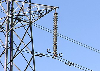 Suspension insulator string (the vertical string of discs) on a 275 kV suspension pylon
 -
 Suspended glass disc insulator unit used in suspension insulator strings for high voltage transmission lines


History

The first electrical systems to make use of insulators were
The first glass insulators used in large quantities had an unthreaded pinhole. These pieces of glass were positioned on a tapered wooden pin, vertically extending upwards from the pole's crossarm (commonly only two insulators to a pole and maybe one on top of the pole itself). Natural contraction and expansion of the wires tied to these "threadless insulators" resulted in insulators unseating from their pins, requiring manual reseating.
Amongst the first to produce ceramic insulators were companies in the United Kingdom, with Stiff and Doulton using stoneware from the mid-1840s, Joseph Bourne (later renamed Denby) producing them from around 1860 and Bullers from 1868. Utility patent number 48,906 was granted to Louis A. Cauvet on 25 July 1865 for a process to produce insulators with a threaded pinhole: pin-type insulators still have threaded pinholes.
The invention of suspension-type insulators made high-voltage power transmission possible. As transmission line voltages reached and passed 60,000 volts, the insulators required become very large and heavy, with insulators made for a safety margin of 88,000 volts being about the practical limit for manufacturing and installation. Suspension insulators, on the other hand, can be connected into strings as long as required for the line's voltage.
A large variety of telephone, telegraph and power insulators have been made; some people collect them, both for their historic interest and for the aesthetic quality of many insulator designs and finishes. One collectors organisation is the US National Insulator Association, which has over 9,000 members.[17]
Insulation of antennas

Often a
These insulators also have to be equipped with overvoltage protection equipment. For the dimensions of the guy insulation, static charges on guys have to be considered. For high masts, these can be much higher than the voltage caused by the transmitter, requiring guys divided by insulators in multiple sections on the highest masts. In this case, guys which are grounded at the anchor basements via a coil - or if possible, directly - are the better choice.
See also
- Stephen Gray – English physicist
- Dielectric material
- Electrical conductivity
Notes
- ISBN 978-81-224-1536-0.
- ISBN 978-1-135-07113-4.
- .
- .
- PMID 28428625.
- ^ Bernhard, Frank; Bernhard, Frank H. (1921). EMF Electrical Year Book. Electrical Trade Pub. Co. p. 822.
- ^ "Understanding IEC Appliance Insulation Classes: I, II and III". Fidus Power. 6 July 2018. Archived from the original on 17 February 2020. Retrieved 16 October 2018.
- ^ "Electrical Porcelain Insulators" (PDF). Product spec sheet. Universal Clay Products, Ltd. Archived from the original (PDF) on 2009-02-20. Retrieved 2008-10-19.
- ^ Cotton, H. (1958). The Transmission and Distribution of Electrical Energy. London: English Univ. Press. copied on Insulator Usage, A.C. Walker's Insulator Information page
- ISBN 978-0-12-812644-8.
Composite insulators can take wind and rain and have good self-cleaning performance under wind and rain, so need checking for pollution only once every 4–5 years, and requiring less time for the repair and power interruption.
- ^ Holtzhausen, J.P. "High Voltage Insulators" (PDF). IDC Technologies. Archived from the original (PDF) on 2014-05-14. Retrieved 2008-10-17.
- ^ IEC 60137:2003. 'Insulated bushings for alternating voltages above 1,000 V.' IEC, 2003.
- ISBN 0-07-020974-X, pages 14-153, 14-154
- ISBN 0-8493-8578-4.
- ISBN 978-81-8431-271-3.
- ^ "Insulators : National Insulator Association Home Page". www.nia.org. Retrieved 2017-12-12.
References
- Taylor, Sue (May 2003). Bullers of Milton. Churnet Valley Books. ISBN 978-1-897949-96-2.
- Function of Grading rings to Composite Insulator
- M. Shakiba, F.; M, S. Azizi; M., Zhou (Oct 2022). "A Transfer Learning-Based Method to Detect Insulator Faults of High-Voltage Transmission Lines via Aerial Images: Distinguishing Intact and Broken Insulator Images". Artificial Intelligence Review. 8 (4): 15–25. S2CID 252999399.
| States of matter | |||||||||
|---|---|---|---|---|---|---|---|---|---|
| Phase phenomena |
| ||||||||
| Electrons in solids |
| ||||||||
| Magnetic phases | |||||||||
| Quasiparticles | |||||||||
| Soft matter | |||||||||
| Authority control databases: National |
|---|