
Third rail
This article needs additional citations for verification. (June 2021) |
.jpg)
A third rail, also known as a live rail, electric rail or conductor rail, is a method of providing
Modern tram systems with street-running, avoid the risk of electrocution by the exposed electric rail by implementing a segmented ground-level power supply, where each segment is electrified only while covered by a vehicle which is using its power.[1]
The third-rail system of electrification is not related to the third rail used in dual-gauge railways.
Description
Third-rail systems are a means of providing electric traction power to trains using an additional rail (called a "conductor rail") for the purpose. On most systems, the conductor rail is placed on the sleeper ends outside the running rails, but in some systems a central conductor rail is used. The conductor rail is supported on ceramic insulators (known as "pots"), at top contact or insulated brackets, at bottom contact, typically at intervals of around 10 feet (3.0 m).[clarification needed]
The trains have metal contact blocks called collector shoes (also known as
The conductor rails have to be interrupted at
The position of contact between the train and the rail varies: some of the earliest systems used top contact, but later developments use side or bottom contact, which enabled the conductor rail to be covered, protecting track workers from accidental contact and protecting the conductor rail from frost, ice, snow and leaf-fall.[3]
Gallery
- Descriptions
-
-
 Third rail (top) atBloor-Yonge station (Line 1) on the Toronto subway. Energized at 600 volts DC, the third rail provides electrical power to the power-train, and ancillariesof the subway cars.
 -
 contact shoeis between the pair of rubber wheels.
 -
 London Stansted Airport people mover with central rail power feed
 -
 London Stansted Airport people mover, showing rail switch


Advantages and disadvantages
Safety

Because third-rail systems, which are located close to the ground, present
The electrified rail threatens
There is also a risk of pedestrians walking onto the tracks at
The end ramps of conductor rails (where they are interrupted, or change sides) present a practical limitation on speed due to the mechanical impact of the shoe, and 161 km/h (100 mph) is considered the upper limit of practical third-rail operation. The world speed record for a third rail train is 175 km/h (109 mph) attained on 11 April 1988 by a British Class 442 EMU.[5]
In the event of a collision with a foreign object, the beveled end ramps of bottom running systems can facilitate the hazard of having the third rail penetrate the interior of a passenger car. This is believed to have contributed to the death of five passengers in the Valhalla train crash of 2015.[6]
Modern systems, such as
Weather effects
Third-rail systems using top contact are prone to accumulations of snow, or ice formed from refrozen snow, and this can interrupt operations. Some systems operate dedicated de-icing trains to deposit an oily fluid or antifreeze (such as propylene glycol) on the conductor rail to prevent the frozen build-up. The third rail can also be heated to alleviate the problem of ice.
Unlike overhead line equipment, third-rail systems are not susceptible to strong winds or
Gaps
Depending on train and track geometry, gaps in the conductor rail (e.g., at level crossings and junctions) could allow a train to stop in a position where all of its power pickup shoes are in gaps, so that no traction power is available. The train is then said to be "gapped". Another train must then be brought up behind the stranded train to push it on to the conductor rail, or a jumper cable may be used to supply enough power to the train to get one of its contact shoes back on the live rail. Avoiding this problem requires a minimum length of trains that can be run on a line. Locomotives have either had the backup of an on-board diesel engine system (e.g., British Rail Class 73), or have been connected to shoes on the rolling stock (e.g. Metropolitan Railway).
Running rails for power supply
The first idea for feeding electricity to a train from an external source was by using both rails on which a train runs, whereby each rail is a conductor for each polarity, and is insulated by the
Shoe contact
The third rail is usually located outside the two running rails, but on some systems it is mounted between them. The electricity is transmitted to the train by means of a
Contact shoe gallery
- Contact shoes
-
![Contact shoe on Metro-North M8 railcar, designed for both over- and under-running third rail.[10]](//upload.wikimedia.org/wikipedia/commons/thumb/0/09/M8_railcar_-9101_contact_shoe%2C_September_2016.jpg/212px-M8_railcar_-9101_contact_shoe%2C_September_2016.jpg)
-
 Acontact shoe for top-contact third rail on SEPTA's Norristown High Speed Line(third rail not visible)
 -
 Third railChicago 'L'car
![Contact shoe on Metro-North M8 railcar, designed for both over- and under-running third rail.[10]](/File:M8_railcar_-9101_contact_shoe,_September_2016.jpg)


Electrical considerations and alternative technologies
Electric traction trains (using electric power generated at a remote power station and transmitted to the trains) are considerably more cost-effective than diesel or steam units, where separate power units must be carried on each train. This advantage is especially marked in urban and rapid transit systems with a high traffic density.
Because of mechanical limitations on the contact to the third rail, trains that use this method of power supply achieve lower speeds than those using
The third rail is an alternative to
All third-rail systems throughout the world are energised with DC supplies. Some of the reasons for this are historical. Early traction engines were DC motors, and the then-available rectifying equipment was large, expensive and impractical to install onboard trains. Also, transmission of the relatively high currents required results in higher losses with AC than DC.[11] Substations for a DC system will have to be (typically) about 2 kilometres (1.2 mi) apart, though the actual spacing depends on the carrying capacity, maximum speed, and service frequency of the line.
One method for reducing current losses (and thus increase the spacing of feeder/substations, a major cost in third rail electrification) is to use a composite conductor rail of a hybrid aluminium/steel design. The aluminium is a better conductor of electricity, and a running face of stainless steel gives better wear.
There are several ways of attaching the stainless steel to the aluminium. The oldest is a co-extruded method, where the stainless steel is extruded with the aluminium. This method has suffered, in isolated cases, from de-lamination (where the stainless steel separates from the aluminium); this is said to have been eliminated in the latest co-extruded rails. A second method is an aluminium core, upon which two stainless steel sections are fitted as a cap and linear welded along the centre line of the rail. Because aluminium has a higher
Return current mechanisms
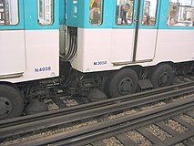
As with overhead wires, the return current usually flows through one or both running rails, and leakage to ground is not considered serious. Where trains run on rubber tyres, as on parts of the Lyon Metro, Paris Métro, Mexico City Metro, Santiago Metro, Sapporo Municipal Subway, and on all of the Montreal Metro and some automated guideway transit systems (e.g. the Astram Line), a live rail must be provided to feed the current. The return is effected through the rails of the conventional track between these guide bars (see rubber-tyred metro).
Another design, with a third rail (current feed, outside the running rails) and fourth rail (current return, midway between the running rails), is used by a few steel-wheel systems; see
Another four-rail system is line M1 of the Milan Metro, where current is drawn by a lateral, flat bar with side contact, with return via a central rail with top contact. Along some sections on the northern part of the line an overhead line is also in place, to allow line M2's trains (that use pantographs and higher voltage, and have no contact shoes) to access a depot located on line M1. In depots, line M1 trains use pantographs because of safety reasons, with transition made near the depots away from revenue tracks.
Aesthetic considerations
Third rail electrification is less visually obtrusive than overhead electrification.[12]
Mixed systems
Several systems use a third rail for part of the route, and other motive power such as overhead
United Kingdom
Several types of British trains have been able to operate on both overhead and third-rail systems, including British Rail Class 313, 319, 325, 350, 365, 375/6, 377/2, 377/5, 377/7, 378/2, 387, 373, 395, 700 and 717 EMUs, as well as Class 92 locomotives.
Network Rail claims to run the world's largest third-rail network.[13]
On the southern region of British Rail, freight yards had[when?] overhead wires to avoid the electrocution hazards of a third rail.[14] The locomotives were fitted with a pantograph as well as pick-up shoes.
Eurostar/High Speed 1
The
The dual-voltage system did cause some problems. Failure to retract the shoes when entering France caused severe damage to the trackside equipment, causing SNCF to install a pair of concrete blocks at the Calais end of both tunnels to break off the third rail shoes if they had not been retracted. An accident occurred in the UK when a Eurostar driver failed to retract the pantograph before entering the third-rail system, damaging a signal gantry and the pantograph.
On 14 November 2007, Eurostar's passenger operations were transferred to St Pancras railway station and maintenance operations to Temple Mills depot, making the 750 V DC third rail collection equipment redundant and the third rail shoes were removed. The trains themselves are no longer fitted with a speedometer capable of measuring the speed in miles per hour (the indication used to automatically change when the collector shoes were deployed).
In 2009, Southeastern began operating domestic services over High Speed 1 trackage from St Pancras using its new Class 395 EMUs. These services operate on the High Speed line as far as Ebbsfleet International or Ashford International, before transferring to the main lines to serve north and mid Kent. As a consequence, these trains are dual-voltage enabled, as the majority of the routes along which they travel are third-rail electrified.
North London Line
In London, the
West London Line
Also in London, the
Thameslink
The cross-city
Northern City
On the Moorgate to Hertford and Welwyn suburban service routes, the East Coast Main Line sections are 25 kV AC, with a changeover to third rail made at Drayton Park railway station. A third rail is still used in the tunnel section of the route, because the size of the tunnels leading to Moorgate station was too small to allow for overhead electrification.
North Downs Line
The North Downs Line is not electrified on those parts of the line where the North Downs service has exclusive use.
The electrified portions of the line are:
- Redhill to Reigate – Allows Southern Railwayservices to run to Reigate. This saves having to turn around terminating services at Redhill where due to the station layout, as the reversal would block nearly all the running lines.
- Shalford Junction to Aldershot South Junction – line shared with South Western Railwayelectric Portsmouth and Aldershot services.
- Wokingham to Reading – line shared with South Western Railway electric services from Waterloo.
- Redhill to Reigate – Allows
Belgium
.jpg)
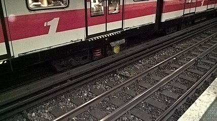
The Brussels Metro uses a 900 V DC third-rail system, placed laterally, with contact by means of a shoe running under the power rail which has an insulating layer at top and sides.
Finland
The
France
The new
The French Culoz–Modane railway was electrified with 1500 V DC third rail, later converted to overhead wires at the same voltage. Stations had overhead wires from the beginning.
The French branch line which serves Chamonix and the Mont Blanc region (Saint-Gervais-le-Fayet to Vallorcine) is third rail (top contact) and metre gauge. It continues in Switzerland, partly with the same third-rail system, partly with an overhead line.
The 63 km (39 mi) long Train Jaune line in the Pyrenees also features a third rail.
Many suburban lines that ran out of the
Netherlands
To mitigate investment costs, the Rotterdam Metro, basically a third-rail-powered system, has been given some outlying branches built on surface tracks as light rail (called sneltram in Dutch), with numerous level crossings protected with barriers and traffic lights. These branches have overhead wires. The RandstadRail project also requires Rotterdam Metro trains to run under wires along the former mainline railways to The Hague and Hook of Holland.
Similarly, in Amsterdam one sneltram route went on
Russian Federation and former Soviet Union
In all
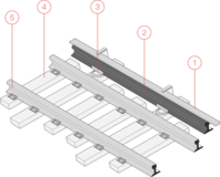
- Third rail schema
-
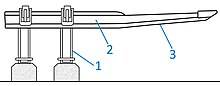 Third rail schema: two brackets and third rail for bottom contact
1) brackets
2) The third rail
3) The contact surface -
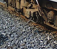
 Bottom contact third rail in thesheath insulator
 -
 Two contact rails at the Rechnoy Vokzal station of the Novosibirsk Metro a station with left-hand platforms.


.jpg)
United States
In New York City, the
The main two stations in New York City – Grand Central and
In New York City (on most of the
Some sections of the former London tram system also used the conduit current collection system, also with some tramcars that could collect power from both overhead and under-road sources.
The
Dual power supply method was also used on some US
Simultaneous use with overhead wire
A railway can be electrified with an
Non-standard voltages
Some high third rail voltages (1000 volts and more) include:
- Hamburg S-Bahn: 1200 V, since 1940
- Manchester–Bury, England: 1200 V (side contact) (Until Metrolink conversion in 1991)
- Culoz–Modane railway, France: 1500 V, 1925–1976
- 5: 1500 V
- Bay Area Rapid Transit, San Francisco, 1000 V[17][18]
In Nazi Germany, a railway system with a 3,000 mm (9 ft 10+1⁄8 in) gauge width was planned. For this Breitspurbahn railway system, electrification with a voltage of 100 kV taken from a third rail was considered, in order to avoid damage to overhead wires from oversize rail-mounted anti-aircraft guns. However, such a power system would not have worked as it is not possible to insulate a third rail for such high voltages in close proximity to the rails. The whole project did not progress any further owing to the onset of World War II.
History
Third-rail electrification systems are, apart from on-board batteries, the oldest means of supplying electric power to trains on railways using their own corridors, particularly in cities. Overhead power supply was initially almost exclusively used on tramway-like railways, though it also appeared slowly on mainline systems.
An experimental electric train using this method of power supply was developed by the German firm of
Also in the 1880s, third-rail systems began to be used in public urban transport. Trams were first to benefit from it: they used conductors in conduit below the road surface (see Conduit current collection), usually on selected parts of the networks. This was first tried in Cleveland (1884) and in Denver (1885) and later spread to many big tram networks (e.g. New York; Chicago; Washington, DC; London; Paris, all of which are closed) and Berlin (the third-rail system in the city was abandoned in the early 20th century after heavy snowfall.) The system was tried in the beachside resort of Blackpool, UK, but was soon abandoned as sand and saltwater were found to enter the conduit and cause breakdowns, and there was a problem with voltage drop. Some sections of tramway track still have the slot rails visible.
A third rail supplied power to the world's first electric underground railway, the
In Paris, a third rail appeared in 1900 in the main-line tunnel connecting the Gare d'Orsay to the rest of the CF Paris-Orléans network. Main-line third-rail electrification was later expanded to some suburban services.
The Woodford haulage system was used on
, with the third rail divided into multiple blocks that could be set to power, coast, or brake by switches in the control center.Top contact or gravity type third rail seems to be the oldest form of power collection. Railways pioneering in using less hazardous types of third rail were the
In 1956, the world's first rubber-tyred railway line, Line 11 of
In 2004, the third-rail technology at street tram lines was in the
Third-rail systems are not considered obsolete.[
- History
-
 With surface contact third and fourth rail systems a heavy "shoe" suspended from a wooden beam attached to the bogies collects power by sliding over the top surface of the electric rail. This view shows a British Rail Class 313 train.
 -
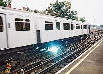 The London Underground uses a four-rail system where both conductor rails are live relative to the running rails, and the positive rail has twice the voltage of the negative rail. Arcs like this are normal and occur when the electric power collection shoes of a train that is drawing power reach the end of a section of conductor rail.
 -
 Conductor rail on theheat and electrical conduction
 -
 Track ofSingapore LRT; the third rail is on the right side
 -
 A train on Milan Metro's Line 1 showing the fourth-rail contact shoe.
 -
 Sapporo Subwaywith a centrally placed guiding/return rail


Model railways
In 1906, the
Märklin three-rail trains use a short pulse at a higher voltage than is used for powering the train, to reverse a relay within the locomotive. Märklin's track does not have an actual third rail; instead, a series of short pins provide the current, taken up by a long "shoe" under the engine. This shoe is long enough to always be in contact with several pins. This is known as the
Many model train sets today use only two rails, usually associated with Z, N, HO or G-Gauge systems. These are typically powered by direct current (DC) where the voltage and polarity of the current controls the speed and direction of the DC motor in the train. A growing exception is Digital Command Control (DCC), where bi-polar DC is delivered to the rails at a constant voltage, along with digital signals that are decoded within the locomotive. The bi-polar DC carries digital information to indicate the command and the locomotive that is being commanded, even when multiple locomotives are present on the same track. The aforementioned Lionel O-Gauge system remains popular today as well with its three rail track and AC power implementation.
Some model railroads realistically mimic the third rail configurations of their full-sized counterparts although nearly all do not draw power from the third rail.
See also
- Conduit current collection
- Contact shoe
- Fourth rail
- Ground-level power supply
- Guide bar
- Initial Electrification Experiments NY NH HR
- Insulator (electricity)
- Linear motor
- List of railway electrification systems
- List of rail transport systems using third rail
- List of suburban and commuter rail systems
- Online Electric Vehicle
- Overhead conductor rails
- Railway electrification in Great Britain
- Rubber-tyred metro
- Stud contact system
- Third rail (model rail)
- Third-rail power for trams
References
- ^ a b Christeller, Reinhard (17 June 2020). "Innovative power supply technologies for traction systems in public transport". Urban Transport. Retrieved 8 February 2022.
- ^ Forman, Keith G. (16 April 2013). Aluminium/Stainless Steel Conductor Technology: A Case for its Adoption in the US. 2013 IEE/ASME Joint Rail Conference.
- ^ a b Middleton, William D. (9 September 2002). "Railroad Standardization – Notes on Third Rail Electrification". Railway & Locomotive Historical Society Newsletter. 27 (4): 10–11.
- ^ Lee v. Chicago Transit Authority, 152 Ill.2d 432, 605 N.E.2d 493 (1992).
- ^ "Class 442 Feature – The Early Years". extra.southernelectric.org.uk. Retrieved 23 June 2021.
- ^ "Investigating the Metro-North Crash". The New York Times. 4 February 2015. Retrieved 15 February 2015.
- ^ "Metro-North's 3rd rail was designed for safety".
- ^ Middleton, William D. (4 September 2002). "Railroad Standardization – Notes on Third Rail Electrification" (PDF). Railway & Locomotive Historical Society Newsletter. 27 (4): 10–11. Archived from the original (PDF) on 16 March 2009. Retrieved 22 August 2009.
- ^ "Trains : Docklands Light Railway : TheTrams.co.uk".
- ^ "Third-rail current collectors". schunk-carbontechnology.com.
- ^ Yadav, Anil. "Traction choices: overhead ac vs third rail dc". Retrieved 3 September 2018.
- ^ Business Standard, April 2016
- ^ "Third rail - Network Rail". Networkrail.co.uk. Retrieved 12 September 2022.
- ISBN 978-1-84797-547-8.
- ^ "Track and depot". Helsinki City Transport. City of Helsinki. Retrieved 5 March 2021.
- ^ "NJ Transit in US initiates testing of dual-power locomotives". www.railway-technology.com. 7 April 2021. Retrieved 5 September 2021.
- ^ System Facts
- ^ "BART – Car Types". Bay Area Rapid Transit. Retrieved 23 August 2009.
- ^ F. E. Woodford, An Electric Haulage System: Controlling Cars at a Distance From a Central Station, Scientific American Supplement, No. 2115, 15 July 1916; page 40.
- ^ An Electrically-Operated Quarry and Plant for Production of Broken Stone at Gary, Ill., Engineering News, Vol. 62, No. 17; 21 Oct. 1909; page 421-428.
- ISBN 9780823222957.
External links
- Thomas Edison's third rail patent (1882)
- Lightrail without wires – Paper on Bordeaux' new Tram with street level third rail (by the Transportation Research Board of the National Academies)
- Details of the UK 3rd/4th rail design.
- Morrison-Knudsen 1992
| Authority control databases: National |
|---|