
Microscopy


Microscopy is the technical field of using
Optical microscopy and electron microscopy involve the
History
._Natuurkundige_te_Delft_Rijksmuseum_SK-A-957.jpeg)
The field of microscopy (
Optical microscopy

Optical or light microscopy involves passing
Limitations
Limitations of standard optical microscopy (
- The technique can only image dark or strongly refracting objects effectively.
- There is a diffraction-limited resolution depending on incident wavelength; in visible range, the resolution of optical microscopy is limited to approximately 0.2 micrometres (see: microscope) and the practical magnification limit to ~1500x.[13]
- Out-of-focus light from points outside the focal plane reduces image clarity.[14]
Live cells in particular generally lack sufficient contrast to be studied successfully, since the internal structures of the cell are colorless and transparent. The most common way to increase contrast is to
Techniques
To improve specimen contrast or highlight structures in a sample, special techniques must be used. A huge selection of microscopy techniques are available to increase contrast or label a sample.
- Four examples of transillumination techniques used to generate contrast in a sample of tissue paper. 1.559 μm/pixel.
-
 Bright field illumination, sample contrast comes from absorbanceof light in the sample
 -
 Cross-polarized light illumination, sample contrast comes from rotation of polarized light through the sample
 -
 scatteredby the sample
 -
 interferenceof different path lengths of light through the sample


Bright field
Bright field microscopy is the simplest of all the light microscopy techniques. Sample illumination is via transmitted white light, i.e. illuminated from below and observed from above. Limitations include low contrast of most biological samples and low apparent resolution due to the blur of out-of-focus material. The simplicity of the technique and the minimal sample preparation required are significant advantages.[citation needed]
Oblique illumination
The use of oblique (from the side) illumination gives the image a three-dimensional appearance and can highlight otherwise invisible features. A more recent technique based on this method is Hoffmann's modulation contrast, a system found on inverted microscopes for use in cell culture. Oblique illumination enhances contrast even in clear specimens; however, because light enters off-axis, the position of an object will appear to shift as the focus is changed. This limitation makes techniques like optical sectioning or accurate measurement on the z-axis impossible.
Dark field
Dark field microscopy is a technique for improving the contrast of unstained, transparent specimens.[16] Dark field illumination uses a carefully aligned light source to minimize the quantity of directly transmitted (unscattered) light entering the image plane, collecting only the light scattered by the sample. Dark field can dramatically improve image contrast – especially of transparent objects – while requiring little equipment setup or sample preparation. However, the technique suffers from low light intensity in the final image of many biological samples and continues to be affected by low apparent resolution.

Rheinberg illumination is a variant of dark field illumination in which transparent, colored filters are inserted just before the
Dispersion staining
Dispersion staining is an optical technique that results in a colored image of a colorless object. This is an optical staining technique and requires no stains or dyes to produce a color effect. There are five different microscope configurations used in the broader technique of dispersion staining. They include brightfield Becke line, oblique, darkfield, phase contrast, and objective stop dispersion staining.
Phase contrast
- In electron microscopy: Phase-contrast imaging
More sophisticated techniques will show proportional differences in optical density. Phase contrast is a widely used technique that shows differences in refractive index as difference in contrast. It was developed by the Dutch physicist Frits Zernike in the 1930s (for which he was awarded the Nobel Prize in 1953). The nucleus in a cell for example will show up darkly against the surrounding cytoplasm. Contrast is excellent; however it is not for use with thick objects. Frequently, a halo is formed even around small objects, which obscures detail. The system consists of a circular annulus in the condenser, which produces a cone of light. This cone is superimposed on a similar sized ring within the phase-objective. Every objective has a different size ring, so for every objective another condenser setting has to be chosen. The ring in the objective has special optical properties: it, first of all, reduces the direct light in intensity, but more importantly, it creates an artificial phase difference of about a quarter wavelength. As the physical properties of this direct light have changed, interference with the diffracted light occurs, resulting in the phase contrast image. One disadvantage of phase-contrast microscopy is halo formation (halo-light ring).
Differential interference contrast
Superior and much more expensive is the use of interference contrast. Differences in optical density will show up as differences in relief. A nucleus within a cell will actually show up as a globule in the most often used differential interference contrast system according to Georges Nomarski. However, it has to be kept in mind that this is an optical effect, and the relief does not necessarily resemble the true shape. Contrast is very good and the condenser aperture can be used fully open, thereby reducing the depth of field and maximizing resolution.
The system consists of a special prism (Nomarski prism, Wollaston prism) in the condenser that splits light in an ordinary and an extraordinary beam. The spatial difference between the two beams is minimal (less than the maximum resolution of the objective). After passage through the specimen, the beams are reunited by a similar prism in the objective.
In a homogeneous specimen, there is no difference between the two beams, and no contrast is being generated. However, near a refractive boundary (say a nucleus within the cytoplasm), the difference between the ordinary and the extraordinary beam will generate a relief in the image. Differential interference contrast requires a
Note: In cases where the optical design of a microscope produces an appreciable lateral separation of the two beams we have the case of classical interference microscopy, which does not result in relief images, but can nevertheless be used for the quantitative determination of mass-thicknesses of microscopic objects.
Interference reflection
An additional technique using interference is interference reflection microscopy (also known as reflected interference contrast, or RIC). It relies on cell adhesion to the slide to produce an interference signal. If there is no cell attached to the glass, there will be no interference.
Interference reflection microscopy can be obtained by using the same elements used by DIC, but without the prisms. Also, the light that is being detected is reflected and not transmitted as it is when DIC is employed.
Fluorescence
When certain compounds are illuminated with high energy light, they emit light of a lower frequency. This effect is known as fluorescence. Often specimens show their characteristic autofluorescence image, based on their chemical makeup.
This method is of critical importance in the modern life sciences, as it can be extremely sensitive, allowing the detection of single molecules. Many fluorescent dyes can be used to stain structures or chemical compounds. One powerful method is the combination of antibodies coupled to a fluorophore as in immunostaining. Examples of commonly used fluorophores are fluorescein or rhodamine.
The antibodies can be tailor-made for a chemical compound. For example, one strategy often in use is the artificial production of proteins, based on the genetic code (DNA). These proteins can then be used to immunize rabbits, forming antibodies which bind to the protein. The antibodies are then coupled chemically to a fluorophore and used to trace the proteins in the cells under study.
Highly efficient fluorescent proteins such as the green fluorescent protein (GFP) have been developed using the molecular biology technique of gene fusion, a process that links the expression of the fluorescent compound to that of the target protein. This combined fluorescent protein is, in general, non-toxic to the organism and rarely interferes with the function of the protein under study. Genetically modified cells or organisms directly express the fluorescently tagged proteins, which enables the study of the function of the original protein in vivo.
Growth of protein crystals results in both protein and salt crystals. Both are colorless and microscopic. Recovery of the protein crystals requires imaging which can be done by the intrinsic fluorescence of the protein or by using transmission microscopy. Both methods require an ultraviolet microscope as proteins absorbs light at 280 nm. Protein will also fluorescence at approximately 353 nm when excited with 280 nm light.[18]
Since fluorescence emission differs in wavelength (color) from the excitation light, an ideal fluorescent image shows only the structure of interest that was labeled with the fluorescent dye. This high specificity led to the widespread use of fluorescence light microscopy in biomedical research. Different fluorescent dyes can be used to stain different biological structures, which can then be detected simultaneously, while still being specific due to the individual color of the dye.
To block the excitation light from reaching the observer or the detector,
See also: total internal reflection fluorescence microscope Neuroscience
Confocal
Confocal laser scanning microscopy uses a focused laser beam (e.g. 488 nm) that is scanned across the sample to excite fluorescence in a point-by-point fashion. The emitted light is directed through a pinhole to prevent out-of-focus light from reaching the detector, typically a photomultiplier tube. The image is constructed in a computer, plotting the measured fluorescence intensities according to the position of the excitation laser. Compared to full sample illumination, confocal microscopy gives slightly higher lateral resolution and significantly improves optical sectioning (axial resolution). Confocal microscopy is, therefore, commonly used where 3D structure is important.
A subclass of confocal microscopes are spinning disc microscopes which are able to scan multiple points simultaneously across the sample. A corresponding disc with pinholes rejects out-of-focus light. The light detector in a spinning disc microscope is a digital camera, typically EM-CCD or sCMOS.
Two-photon microscopy
A two-photon microscope is also a laser-scanning microscope, but instead of UV, blue or green laser light, a pulsed infrared laser is used for excitation. Only in the tiny focus of the laser is the intensity high enough to generate fluorescence by two-photon excitation, which means that no out-of-focus fluorescence is generated, and no pinhole is necessary to clean up the image.[19] This allows imaging deep in scattering tissue, where a confocal microscope would not be able to collect photons efficiently.[20] Two-photon microscopes with wide-field detection are frequently used for functional imaging, e.g. calcium imaging, in brain tissue.[21] They are marketed as Multiphoton microscopes by several companies, although the gains of using 3-photon instead of 2-photon excitation are marginal.
Single plane illumination microscopy and light sheet fluorescence microscopy
Using a plane of light formed by focusing light through a cylindrical lens at a narrow angle or by scanning a line of light in a plane perpendicular to the axis of objective, high resolution optical sections can be taken.[22][23][24] Single plane illumination, or light sheet illumination, is also accomplished using beam shaping techniques incorporating multiple-prism beam expanders.[25][26] The images are captured by CCDs. These variants allow very fast and high signal to noise ratio image capture.
Wide-field multiphoton microscopy
Deconvolution
Fluorescence microscopy is a powerful technique to show specifically labeled structures within a complex environment and to provide three-dimensional information of biological structures. However, this information is blurred by the fact that, upon illumination, all fluorescently labeled structures emit light, irrespective of whether they are in focus or not. So an image of a certain structure is always blurred by the contribution of light from structures that are out of focus. This phenomenon results in a loss of contrast especially when using objectives with a high resolving power, typically oil immersion objectives with a high numerical aperture.

However, blurring is not caused by random processes, such as light scattering, but can be well defined by the optical properties of the image formation in the microscope imaging system. If one considers a small fluorescent light source (essentially a bright spot), light coming from this spot spreads out further from our perspective as the spot becomes more out of focus. Under ideal conditions, this produces an "hourglass" shape of this point source in the third (axial) dimension. This shape is called the point spread function (PSF) of the microscope imaging system. Since any fluorescence image is made up of a large number of such small fluorescent light sources, the image is said to be "convolved by the point spread function". The mathematically modeled PSF of a terahertz laser pulsed imaging system is shown on the right.
The output of an imaging system can be described using the equation:

Where n is the additive noise.[32] Knowing this point spread function[33] means that it is possible to reverse this process to a certain extent by computer-based methods commonly known as deconvolution microscopy.[34] There are various algorithms available for 2D or 3D deconvolution. They can be roughly classified in nonrestorative and restorative methods. While the nonrestorative methods can improve contrast by removing out-of-focus light from focal planes, only the restorative methods can actually reassign light to its proper place of origin. Processing fluorescent images in this manner can be an advantage over directly acquiring images without out-of-focus light, such as images from confocal microscopy, because light signals otherwise eliminated become useful information. For 3D deconvolution, one typically provides a series of images taken from different focal planes (called a Z-stack) plus the knowledge of the PSF, which can be derived either experimentally or theoretically from knowing all contributing parameters of the microscope.
Sub-diffraction techniques
A multitude of super-resolution microscopy techniques have been developed in recent times which circumvent the diffraction limit.
This is mostly achieved by imaging a sufficiently static sample multiple times and either modifying the excitation light or observing stochastic changes in the image. The deconvolution methods described in the previous section, which removes the PSF induced blur and assigns a mathematically 'correct' origin of light, are used, albeit with slightly different understanding of what the value of a pixel mean. Assuming most of the time, one single fluorophore contributes to one single blob on one single taken image, the blobs in the images can be replaced with their calculated position, vastly improving resolution to well below the diffraction limit.
To realize such assumption, Knowledge of and chemical control over fluorophore photophysics is at the core of these techniques, by which resolutions of ~20 nanometers are obtained.[35][36]
Serial time-encoded amplified microscopy
Serial time encoded amplified microscopy (STEAM) is an imaging method that provides ultrafast shutter speed and frame rate, by using optical image amplification to circumvent the fundamental trade-off between sensitivity and speed, and a single-pixel photodetector to eliminate the need for a detector array and readout time limitations[37] The method is at least 1000 times faster than the state-of-the-art CCD and CMOS cameras. Consequently, it is potentially useful for scientific, industrial, and biomedical applications that require high image acquisition rates, including real-time diagnosis and evaluation of shockwaves, microfluidics, MEMS, and laser surgery.[38]
Extensions
Most modern instruments provide simple solutions for micro-photography and image recording electronically. However such capabilities are not always present and the more experienced microscopist may prefer a hand drawn image to a photograph. This is because a microscopist with knowledge of the subject can accurately convert a three-dimensional image into a precise two-dimensional drawing. In a photograph or other image capture system however, only one thin plane is ever in good focus.[citation needed]
The creation of accurate micrographs requires a microscopical technique using a monocular eyepiece. It is essential that both eyes are open and that the eye that is not observing down the microscope is instead concentrated on a sheet of paper on the bench besides the microscope. With practice, and without moving the head or eyes, it is possible to accurately trace the observed shapes by simultaneously "seeing" the pencil point in the microscopical image.[citation needed]
It is always less tiring to observe with the microscope focused so that the image is seen at infinity and with both eyes open at all times. [citation needed]
Other enhancements
Microspectroscopy:spectroscopy with a microscope
X-ray
As resolution depends on the wavelength of the light. Electron microscopy has been developed since the 1930s that use electron beams instead of light. Because of the much smaller wavelength of the electron beam, resolution is far higher.
Though less common,
Electron microscopy
Until the invention of sub-diffraction microscopy, the wavelength of the light limited the resolution of traditional microscopy to around 0.2 micrometers. In order to gain higher resolution, the use of an electron beam with a far smaller wavelength is used in electron microscopes.
- Transmission electron microscopy (TEM) is quite similar to the compound light microscope, by sending an electron beam through a very thin slice of the specimen. The resolution limit in 2005 was around 0.05 [dubious – discuss] nanometer and has not increased appreciably since that time.
- Scanning electron microscopy (SEM) visualizes details on the surfaces of specimens and gives a very nice 3D view. It gives results much like those of the stereo light microscope. The best resolution for SEM in 2011 was 0.4 nanometer.
Electron microscopes equipped for X-ray spectroscopy can provide qualitative and quantitative elemental analysis. This type of electron microscope, also known as analytical electron microscope, can be a very powerful tool for investigation of nanomaterials.[39]
Scanning probe microscopy
This is a sub-diffraction technique. Examples of scanning probe microscopes are the
Ultrasonic force
Ultrasonic force microscopy allows the local mapping of elasticity in atomic force microscopy by the application of ultrasonic vibration to the cantilever or sample. To analyze the results of ultrasonic force microscopy in a quantitative fashion, a force-distance curve measurement is done with ultrasonic vibration applied to the cantilever base, and the results are compared with a model of the cantilever dynamics and tip-sample interaction based on the finite-difference technique.
Ultraviolet microscopy
Ultraviolet microscopes have two main purposes. The first is to use the shorter wavelength of ultraviolet electromagnetic energy to improve the image resolution beyond that of the diffraction limit of standard optical microscopes. This technique is used for non-destructive inspection of devices with very small features such as those found in modern semiconductors. The second application for UV microscopes is contrast enhancement where the response of individual samples is enhanced, relative to their surrounding, due to the interaction of light with the molecules within the sample itself. One example is in the growth of protein crystals. Protein crystals are formed in salt solutions. As salt and protein crystals are both formed in the growth process, and both are commonly transparent to the human eye, they cannot be differentiated with a standard optical microscope. As the tryptophan of protein absorbs light at 280 nm, imaging with a UV microscope with 280 nm bandpass filters makes it simple to differentiate between the two types of crystals. The protein crystals appear dark while the salt crystals are transparent.
Infrared microscopy
The term infrared microscopy refers to microscopy performed at infrared wavelengths. In the typical instrument configuration, a Fourier Transform Infrared Spectrometer (FTIR) is combined with an optical microscope and an infrared detector. The infrared detector can be a single point detector, a linear array or a 2D focal plane array. FTIR provides the ability to perform chemical analysis via infrared spectroscopy and the microscope and point or array detector enable this chemical analysis to be spatially resolved, i.e. performed at different regions of the sample. As such, the technique is also called infrared microspectroscopy[40][41] An alternative architecture called
IR versions of sub-diffraction microscopy also exist. that provide nanoscale spatial resolution at IR wavelengths.
Digital holographic microscopy
In
DHM can operate both in reflection and transmission mode. In reflection mode, the phase shift image provides a relative distance measurement and thus represents a topography map of the reflecting surface. In transmission mode, the phase shift image provides a label-free quantitative measurement of the optical thickness of the specimen. Phase shift images of biological cells are very similar to images of stained cells and have successfully been analyzed by high content analysis software.
A unique feature of DHM is the ability to adjust focus after the image is recorded, since all focus planes are recorded simultaneously by the hologram. This feature makes it possible to image moving particles in a volume or to rapidly scan a surface. Another attractive feature is The ability of DHM to use low cost optics by correcting optical aberrations by software.
Digital pathology (virtual microscopy)
Digital pathology is an image-based information environment enabled by computer technology that allows for the management of information generated from a digital slide. Digital pathology is enabled in part by virtual microscopy, which is the practice of converting glass slides into digital slides that can be viewed, managed, and analyzed.
Laser microscopy
Laser microscopy is a rapidly growing field that uses laser illumination sources in various forms of microscopy.[44] For instance, laser microscopy focused on biological applications uses ultrashort pulse lasers, in a number of techniques labeled as nonlinear microscopy, saturation microscopy, and two-photon excitation microscopy.[45]
High-intensity, short-pulse laboratory x-ray lasers have been under development for several years. When this technology comes to fruition, it will be possible to obtain magnified three-dimensional images of elementary biological structures in the living state at a precisely defined instant. For optimum contrast between water and protein and for best sensitivity and resolution, the laser should be tuned near the nitrogen line at about 0.3 nanometers. Resolution will be limited mainly by the hydrodynamic expansion that occurs while the necessary number of photons is being registered.[46] Thus, while the specimen is destroyed by the exposure, its configuration can be captured before it explodes.[47][48][49][50][51][52][excessive citations]
Scientists have been working on practical designs and prototypes for x-ray holographic microscopes, despite the prolonged development of the appropriate laser.[53][54][55][56][57][58][59][60][excessive citations]
Photoacoustic microscopy

A microscopy technique relying on the photoacoustic effect,[61] i.e. the generation of (ultra)sound caused by light absorption. A focused and intensity modulated laser beam is raster scanned over a sample. The generated (ultra)sound is detected via an ultrasound transducer. Commonly piezoelectric ultrasound transducers are employed.[62]
The image contrast is related to the sample's absorption coefficient . This is in contrast to bright or dark field microscopy, where the image contrast is due to transmittance or scattering. In principle, the contrast of fluorescence microscopy is proportional to the sample's absorption too. However, in fluorescence microscopy the fluorescence quantum yield needs to be unequal to zero in order that a signal can be detected. In photoacoustic microscopy, however, every absorbing substance gives a photoacoustic signal which is proportional to


Here is the Grüneisen coefficient, is the laser's photon energy and is the sample's band gap energy. Therefore, photoacoustic microscopy seems well suited as a complementary technique to fluorescence microscopy, as a high fluorescence quantum yield leads to high fluorescence signals and a low fluorescence quantum yield leads to high photoacoustic signals.


Neglecting non-linear effects, the lateral resolution dx is limited by the

where is the wavelength of the excitation laser and NA is the numerical aperture of the objective lens. The Abbe diffraction limit holds if the incoming wave front is parallel. In reality, however, the laser beam profile is Gaussian. Therefore, in order to the calculate the achievable resolution, formulas for truncated Gaussian beams have to be used.[63]

Amateur microscopy
Amateur Microscopy is the investigation and observation of
While microscopy is a central tool in the documentation of biological specimens, it is often insufficient to justify the description of a new species based on microscopic investigations alone. Often genetic and biochemical tests are necessary to confirm the discovery of a new species. A laboratory and access to academic literature is a necessity. There is, however, one advantage that amateurs have above professionals: time to explore their surroundings. Often, advanced amateurs team up with professionals to validate their findings and possibly describe new species.
In the late 1800s, amateur microscopy became a popular hobby in the United States and Europe. Several 'professional amateurs' were being paid for their sampling trips and microscopic explorations by philanthropists, to keep them amused on the Sunday afternoon (e.g., the diatom specialist A. Grunow, being paid by (among others) a Belgian industrialist). Professor John Phin published "Practical Hints on the Selection and Use of the Microscope (Second Edition, 1878)," and was also the editor of the "American Journal of Microscopy."
Examples of amateur microscopy images:
-
 "house bee" Mouth 100X
 -
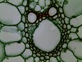 Rice Stem cs 400X
 -
 Rabbit Testis 100X
 -
 Fern Prothallium 400X


Application in forensic science
Microscopy has applications in the forensic sciences.[64] The microscope can detect, resolve and image the smallest items of evidence, often without any alteration or destruction. The microscope is used to identify and compare fibers, hairs, soils, and dust...etc.
In ink markings, blood stains or bullets, no specimen treatment is required and the evidence shows directly from microscopical examination. For traces of particular matter, the sample preparation must be done before microscopical examination occurs.[clarification needed]
Light microscopes are the most use in forensics, using photons to form images, microscopes which are most applicable for examining forensic specimens are as follows:[65]
1. The compound microscope
2. The comparison microscope
3. The stereoscopic microscope
4. The polarizing microscope
5. The micro spectrophotometer
This diversity of the types of microscopes in forensic applications comes mainly from their magnification ranges, which are (1- 1200X), (50 -30,000X) and (500- 250,000X) for the optical microscopy, SEM and TEM respectively.[65]
See also
- List of materials analysis methods
- Digital microscope
- Digital pathology
- Imaging cycler microscopy
- Infinity correction
- Interferometric microscopy
- Köhler illumination
- List of microscopists
- Microdensitometer
- Timeline of microscope technology
- Two-photon excitation microscopy
- USB microscope
- Van Leeuwenhoek's microscopes
- Van Leeuwenhoek's microscopic discovery of microbial life (microorganisms)
References
- ^ The University of Edinburgh (March 6, 2018). "What is Microscopy?". The University of Edinburgh. Archived from the original on April 10, 2018. Retrieved April 9, 2018.
- ^ Atti Della Fondazione Giorgio Ronchi E Contributi Dell'Istituto Nazionale Di Ottica, Volume 30, La Fondazione-1975, page 554
- ISBN 978-90-6984-615-6. Archivedfrom the original on 15 February 2017.
- ^ William Rosenthal, Spectacles and Other Vision Aids: A History and Guide to Collecting, Norman Publishing, 1996, page 391 - 392
- ^ Robert D. Huerta, Giants of Delft: Johannes Vermeer and the Natural Philosophers : the Parallel Search for Knowledge During the Age of Discovery, Bucknell University Press - 2003, page 126
- ^ A. Mark Smith, From Sight to Light: The Passage from Ancient to Modern Optics, University of Chicago Press - 2014, page 387
- ^ Raymond J. Seeger, Men of Physics: Galileo Galilei, His Life and His Works, Elsevier - 2016, page 24
- ^ J. William Rosenthal, Spectacles and Other Vision Aids: A History and Guide to Collecting, Norman Publishing, 1996, page 391
- ^ Ford, Brian J. (1992). "From Dilettante to Diligent Experimenter: a Reappraisal of Leeuwenhoek as microscopist and investigator". Biology History. 5 (3). Archived from the original on 2021-04-19. Retrieved 2021-04-16.
- ^ Lane, Nick (6 March 2015). "The Unseen World: Reflections on Leeuwenhoek (1677) 'Concerning Little Animal'." Philos Trans R Soc Lond B Biol Sci. 2015 Apr; 370 (1666): 20140344. [doi:10.1098/rstb.2014.0344]
- ^ Abramowitz M, Davidson MW (2007). "Introduction to Microscopy". Molecular Expressions. Archived from the original on 2021-04-27. Retrieved 2007-08-22.
- ^ "Microscope - Compound, Numerical Aperture, and Immersion Microscopy | Britannica". www.britannica.com. Archived from the original on 2023-06-22. Retrieved 2023-06-22.
- ^ Abbe, E. (1874) A contribution to the theory of the microscope and the nature of microscopic vision. Proc. Bristol Nat. Soc. 1, 200–261.
- ISBN 0-387-25921-X.
- ^ Lakowicz, Joseph R. (1999) Principles Of Fluorescence Spectroscopy. New York: Kluwer Academic/Plenum.
- ^ Abramowitz M, Davidson MW (2003-08-01). "Darkfield Illumination". Archived from the original on 2015-11-23. Retrieved 2008-10-21.
- ^ Abramowitz M, Davidson MW (2003-08-01). "Rheinberg Illumination". Archived from the original on 2008-09-29. Retrieved 2008-10-21.
- PMID 20208182.
- S2CID 2414593.
- S2CID 3772937.
- from the original on 2021-05-25. Retrieved 2020-05-20.
- S2CID 12775304.
- PMID 17578115.
- PMID 22567307.
- ^ F. J. Duarte, in High Power Dye Lasers (Springer-Verlag, Berlin,1991) Chapter 2.
- ^ Duarte FJ (1993), Electro-optical interferometric microdensitometer system, US Patent 5255069 Archived 2017-10-13 at the Wayback Machine.
- ^ .
- ^ from the original on 2020-06-20. Retrieved 2019-12-11.
- ^ PMID 22513605.
- PMID 19495022.
- S2CID 124315172.
- ISBN 978-0-470-84473-1.
- PMID 20126241.
- PMID 11730015.
- S2CID 2119158.
- doi:10.1071/CH10284.
- S2CID 4415762.
- S2CID 8077381.
- from the original on 2021-01-26. Retrieved 2019-06-28.
- ^ a b H M Pollock and S G Kazarian, Microspectroscopy in the Mid-Infrared, in Encyclopedia of Analytical Chemistry (Robert A. Meyers, Ed, 1-26 (2014), John Wiley & Sons Ltd,
- ^ ISBN 9780470027318.
- ^ H M Pollock and D A Smith, The use of near-field probes for vibrational spectroscopy and photothermal imaging, in Handbook of vibrational spectroscopy, J.M. Chalmers and P.R. Griffiths (eds), John Wiley & Sons Ltd, Vol. 2, pp. 1472 - 1492 (2002)
- from the original on 2020-11-09. Retrieved 2020-11-02.
- ISBN 9781482261066.
- ISBN 978-1-4200-6009-6.
- OSTI 5998195.
- from the original on 2020-08-04. Retrieved 2019-06-28.
- S2CID 32381820.
- .
- ^ Solem, J. C. (1985). "Microholography". McGraw-Hill Encyclopedia of Science and Technology.
- OSTI 6314558.
- .
- ^ Haddad, W. S.; Solem, J. C.; Cullen, D.; Boyer, K.; Rhodes, C. K. (1987). "A description of the theory and apparatus for digital reconstruction of Fourier transform holograms", Proceedings of Electronics Imaging '87, Nov. 2-5, 1987, Boston; Journal of Electronic Imaging, (Institute for Graphic Communication, Inc., Boston), p. 693.
- ISBN 978-3-662-14490-9.
- ^ Haddad, W. S.; Solem, J. C.; Cullen, D.; Boyer, K.; Rhodes, C. K. (1988). "Design for a Fourier-transform holographic microscope incorporating digital image reconstruction". Proceedings of CLEO '88 Conference on Lasers and Electro-Optics, Anaheim, CA, April, 1988; Optical Society of America, OSA Technical Digest. 7: WS4. Archived from the original on 2016-02-02. Retrieved 2016-01-13.
- ^ Haddad, W. S.; Cullen, D.; Solem, J. C.; Boyer, K.; Rhodes, C. K. (1988). "X-ray Fourier-transform holographic microscope". Proceedings of the OSA Topical Meeting on Short Wavelength Coherent Radiation: Generation and Applications, September 26–29, 1988, Cape Cod, MA., Falcone, R.; Kirz, J.; Eds. (Optical Society of America, Washington, DC): 284–289. Archived from the original on 2016-01-27. Retrieved 2016-01-13.
- S2CID 121807907.
- )
- PMID 20733659.
- S2CID 25231033.
- from the original on 2022-11-27. Retrieved 2019-06-28.
- PMID 24416085.
- PMID 27446698.
- .
- ^ a b Basu S, Millette JR (1986). Electron Microscopy in Forensic Occupational and Environmental Health Sciences. New York: Plenum Press.
Further reading
- Pluta, Maksymilian (1988). Advanced Light Microscopy vol. 1 Principles and Basic Properties. Elsevier. ISBN 978-0-444-98939-0.
- Pluta, Maksymilian (1989). Advanced Light Microscopy vol. 2 Specialised Methods. Elsevier. ISBN 978-0-444-98918-5.
- Bradbury, S.; Bracegirdle, B. (1998). Introduction to Light Microscopy. ISBN 978-0-387-91515-9.
- Inoue, Shinya (1986). Video Microscopy. Plenum Press. ISBN 978-0-306-42120-4.
- Cremer, C.; Cremer, T. (1978). "Considerations on a laser-scanning-microscope with high resolution and depth of field" (PDF). Microscopica Acta. 81 (1): 31–44. PMID 713859. Archived from the original(PDF) on 2016-03-04. Retrieved 2009-12-22. Theoretical basis of super resolution 4Pi microscopy & design of a confocal laser scanning fluorescence microscope
- Willis, Randall C. (2007). "Portraits of life, one molecule at a time". Analytical Chemistry. 79 (5): 1785–8. PMID 17375393., a feature article on sub-diffraction microscopy from the March 1, 2007 issue of Analytical Chemistry
External links
General
- Microscopy glossary, Common terms used in amateur light microscopy.
- Nikon MicroscopyU Extensive information on light microscopy
- Olympus Microscopy Microscopy Resource center
- Carl Zeiss "Microscopy from the very beginning", a step by step tutorial into the basics of microscopy.
- Microscopy in Detail - A resource with many illustrations elaborating the most common microscopy techniques
- Manawatu Microscopy - first known collaboration environment for Microscopy and Image Analysis.
- Audio microscope glossary
Techniques
- Ratio-metric Imaging Applications For Microscopes Examples of Ratiometric Imaging Work on a Microscope
- Interactive Fluorescence Dye and Filter Database Carl Zeiss Interactive Fluorescence Dye and Filter Database.
- New approaches to microscopy Eric Betzig: Beyond the Nobel Prize—New approaches to microscopy.
| Illumination and contrast methods |
|  |
|---|---|---|
| Fluorescence methods | ||
| Sub-diffraction limit techniques | ||
| ||
| Techniques | ||
| Sampling |
| |
| Calibration | ||
| Prominent publications | ||