
Projectional radiography
| Projectional radiography | |
|---|---|
 AP and lateral elbow X-ray | |
| ICD-10-PCS | B?0 |
| ICD-9-CM | 87 |
| OPS-301 code | 3-10...3-13 |
Projectional radiography, also known as conventional radiography,
Equipment
X-ray generator
Projectional radiographs generally use X-rays created by
Grid
An anti-scatter grid may be placed between the patient and the detector to reduce the quantity of scattered x-rays that reach the detector. This improves the contrast resolution of the image, but also increases radiation exposure for the patient.
Detector
Detectors can be divided into two major categories: imaging detectors (such as
Shielding
Image properties

Projectional radiography relies on the characteristics of X-ray radiation (quantity and quality of the beam) and knowledge of how it interacts with human tissue to create diagnostic images. X-rays are a form of ionizing radiation, meaning it has sufficient energy to potentially remove electrons from an atom, thus giving it a charge and making it an ion.
X-ray attenuation
When an exposure is made, X-ray radiation exits the tube as what is known as the primary beam. When the primary beam passes through the body, some of the radiation is absorbed in a process known as attenuation. Anatomy that is denser has a higher rate of attenuation than anatomy that is less dense, so bone will absorb more X-rays than soft tissue. What remains of the primary beam after attenuation is known as the remnant beam. The remnant beam is responsible for exposing the image receptor. Areas on the image receptor that receive the most radiation (portions of the remnant beam experiencing the least attenuation) will be more heavily exposed, and therefore will be processed as being darker. Conversely, areas on the image receptor that receive the least radiation (portions of the remnant beam experience the most attenuation) will be less exposed and will be processed as being lighter. This is why bone, which is very dense, process as being 'white' on radio graphs, and the lungs, which contain mostly air and is the least dense, shows up as 'black'.
Density
Radiographic density is the measure of overall darkening of the image. Density is a logarithmic unit that describes the ratio between light hitting the film and light being transmitted through the film. A higher radiographic density represents more opaque areas of the film, and lower density more transparent areas of the film.
With digital imaging, however, density may be referred to as brightness. The brightness of the radiograph in digital imaging is determined by computer software and the monitor on which the image is being viewed.
Contrast
Contrast is defined as the difference in radiographic density between adjacent portions of the image. The range between black and white on the final radiograph. High contrast, or short-scale contrast, means there is little gray on the radiograph, and there are fewer gray shades between black and white. Low contrast, or long-scale contrast, means there is much gray on the radiograph, and there are many gray shades between black and white.
Closely related to radiographic contrast is the concept of exposure latitude. Exposure latitude is the range of exposures over which the recording medium (image receptor) will respond with a diagnostically useful density; in other words, this is the "flexibility" or "leeway" that a radiographer has when setting his/her exposure factors. Images having a short-scale of contrast will have narrow exposure latitude. Images having long-scale contrast will have a wide exposure latitude; that is, the radiographer will be able to utilize a broader range of technical factors to produce a diagnostic-quality image.
Contrast is determined by the kilovoltage (kV; energy/quality/penetrability) of the x-ray beam and the tissue composition of the body part being radiographed. Selection of look-up tables (LUT) in digital imaging also affects contrast.
Generally speaking, high contrast is necessary for body parts in which bony anatomy is of clinical interest (extremities, bony thorax, etc.). When soft tissue is of interest (ex. abdomen or chest), lower contrast is preferable in order to accurately demonstrate all of the soft tissue tones in these areas.
Geometric magnification

Geometric magnification results from the detector being farther away from the X-ray source than the object. In this regard, the source-detector distance or SDD
The estimated radiographic magnification factor (ERMF) is the ratio of the source-detector distance (SDD) over the source-object distance (SOD).[5] The size of the object is given as:
,
where Sizeprojection is the size of the projection that the object forms on the detector. On lumbar and chest radiographs, it is anticipated that ERMF is between 1.05 and 1.40.[6] Because of the uncertainty of the true size of objects seen on projectional radiography, their sizes are often compared to other structures within the body, such as dimensions of the vertebrae, or empirically by clinical experience.[7]

The source-detector distance (SDD) is roughly related to the source-object distance (SOD)[8] and the object-detector distance (ODD) by the equation SOD + ODD = SDD.
Geometric unsharpness
Geometric unsharpness is caused by the X-ray generator not creating X-rays from a single point but rather from an area, as can be measured as the focal spot size. Geometric unsharpness increases proportionally to the focal spot size, as well as the estimated radiographic magnification factor (ERMF).
Geometric distortion
Organs will have different relative distances to the detector depending on which direction the X-rays come from. For example, chest radiographs are preferably taken with X-rays coming from behind (called a "posteroanterior" or "PA" radiograph). However, in case the patient cannot stand, the radiograph often needs to be taken with the patient lying in a supine position (called a "bedside" radiograph) with the X-rays coming from above ("anteroposterior" or "AP"), and geometric magnification will then cause for example the heart to appear larger than it actually is because it is further away from the detector.[9]
Scatter
In addition to using an anti-scatter grid, increasing the ODD alone can improve image contrast by decreasing the amount of scattered radiation that reaches the receptor. However, this needs to be weighted against increased geometric unsharpness if the SDD is not also proportionally increased.[10]
Imaging variations by target tissue
Projection radiography uses
- Hard tissues such as braking radiation. Bony tissue and metals are denser than the surrounding tissue, and thus by absorbing more of the X-ray photons they prevent the film from getting exposed as much.[11] Wherever dense tissue absorbs or stops the X-rays, the resulting X-ray film is unexposed, and appears translucent blue, whereas the black parts of the film represent lower-density tissues such as fat, skin, and internal organs, which could not stop the X-rays. This is usually used to see bony fractures, foreign objects (such as ingested coins), and used for finding bony pathology such as osteoarthritis, infection (osteomyelitis), cancer (osteosarcoma), as well as growth studies (leg length, achondroplasia, scoliosis, etc.).
- Soft tissues are seen with the same machine as for hard tissues, but a "softer" or less-penetrating X-ray beam is used. Tissues commonly imaged include the lungs and heart shadow in a chest X-ray, the air pattern of the bowel in abdominal X-rays, the soft tissues of the neck, the orbits by a skull X-ray before an MRIto check for radiopaque foreign bodies (especially metal), and of course the soft tissue shadows in X-rays of bony injuries are looked at by the radiologist for signs of hidden trauma (for example, the famous "fat pad" sign on a fractured elbow).
Projectional radiography terminology

NOTE: The simplified word 'view' is often used to describe a radiographic projection.
Plain radiography generally refers to projectional radiography (without the use of more advanced techniques such as computed tomography). Plain radiography can also refer to radiography without a radiocontrast agent or radiography that generates single static images, as contrasted to fluoroscopy.
- AP - Antero-Posterior
- PA - Postero-Anterior
- DP - Dorsal-Plantar
- Lateral - Projection taken with the central ray perpendicular to the midsagittal plane
- Oblique - Projection taken with the central ray at an angle to any of the body planes. Described by the angle of obliquity and the portion of the body the X-ray beam exits; right or left and posterior or anterior. For example, a 45 degree Right Anterior Oblique of the Cervical Spine.
- Flexion - Joint is radiographed while in flexion
- Extension - Joint is radiographed while in extension
- Stress Views - Typically taken of joints with external force applied in a direction that is different from main movement of the joint. Test of stability.
- Weight-bearing - Generally with the subject standing up
- HBL, HRL, HCR or CTL - Horizontal Beam Lateral, Horizontal Ray Lateral, Horizontal Central Ray, or Cross Table Lateral. Used to obtain a lateral projection usually when patients are unable to move.
- Prone - Patient lies on their front
- Supine - Patient lies on the back
- Decubitus - Patient lying down. Further described by the downside body surface: dorsal (backside down), ventral (frontside down), or lateral (left or right side down).
- OM - occipito-mental, an imaginary positioning line extending from the menti (chin) to the occiput (particularly the external occiputal protuberance)
- Cranial or Cephalad - Tube angulation towards the head
- Caudal - Tube angulation towards the feet
By target organ or structure
Breasts

Projectional radiography of the breasts is called
Chest
_chest_radiograph_(X-ray).jpg)
Chest radiographs are used to diagnose many conditions involving the chest wall, including its bones, and also structures contained within the
For some conditions of the chest, radiography is good for screening but poor for diagnosis. When a condition is suspected based on chest radiography, additional imaging of the chest can be obtained to definitively diagnose the condition or to provide evidence in favor of the diagnosis suggested by initial chest radiography. Unless a fractured rib is suspected of being displaced, and therefore likely to cause damage to the lungs and other tissue structures, an X-ray of the chest is not necessary as it will not alter patient management.
Abdomen
In children,
The standard abdominal X-ray protocol is usually a single anteroposterior projection in supine position.[15] A Kidneys, Ureters, and Bladder projection (KUB) is an anteroposterior abdominal projection that covers the levels of the urinary system, but does not necessarily include the diaphragm.
Axial skeleton
Head
- Cerebral angiography allows visualization of blood vessels in and around the brain. A contrast agent is injected prior to the radiographs of the head,
- Orbital radiography, imaging both left and right eye sockets, generally including the frontal and maxillary sinuses.
- X-ray generator and X-ray detectorare simultaneously moved so as to keep a consistent exposure of only the plane of interest during image acquisition.
- Sinus - The standard protocol in the UK is OM with open mouth.[15]
- Facial Bones - The standard protocol in the UK is OM and OM 30°.[15]
In case of trauma, the standard UK protocol is to have a CT scan of the skull instead of projectional radiography.[15] A skeletal survey including the skull can be indicated in for example multiple myeloma.[15]
Other axial skeleton
- The spine (that is, the mSv, comparable to a background radiation equivalent timeof 6 months.
- Cervical spine: The standard projections in the UK AP and Lateral. Peg projection with trauma only. Obliques and Flexion and Extension on special request.[15]In the US, five or six projections are common; a Lateral, two 45 degree obliques, an AP axial (Cephalad), an AP "Open Mouth" for C1-C2, and Cervicothoracic Lateral (Swimmer's) to better visualize C7-T1 if necessary. Special projections include a Lateral with Flexion and Extension of the cervical spine, an Axial for C1-C2 (Fuchs or Judd method), and an AP Axial (Caudad) for articular pillars.
- Thoracic Spine - AP and Lateral in the UK.zygapophysial joint.
- Lumbar Spine - AP and Lateral +/- L5/S1 view in the UK, with obliques and Flexion and Extension requests being rare.[15] In the US, basic projections include an AP, two Obliques, a Lateral, and a Lateral L5-S1 spot to better visualize the L5-S1 interspace. Special projections are AP Right and Left bending, and Laterals with Flexion and Extension.
- Pelvis - AP only in the UK, with SIJ projections (prone) on special request.[15]
- Sacrum and Coccyx: In the US, if both bones are to be examined separate cephalad and caudad AP axial projections are obtained for the sacrum and coccyx respectively as well as a single Lateral of both bones.
- Ribs: In the US, common rib projections are based on the location of the area of interest. These are obtained with shorter wavelengths/higher frequencies/higher levels of radiation than a standard CXR.
- Anterior area of interest - a PA chest X-ray, a PA projection of the ribs, and a 45 degree Anterior Oblique with the non-interest side closest to the image receptor.
- Posterior area of interest - a PA chest X-ray, an AP projection of the ribs, and a 45 degree Posterior Oblique with the side of interest closest to the image receptor.
- Sternum. The standard projections in the UK are PA chest and lateral sternum.[15] In the US, the two basic projections are a 15 to 20 degree Right Anterior Oblique and a Lateral.
- Sternoclavicular Joints - Are usually ordered as a single PA and a Right and Left 15 degree Right Anterior Obliques in the US.
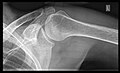
Shoulders
_X-ray_of_a_normal_shoulder.jpg)
These include:
- AP-projection 40° posterior oblique after Grashey
The body has to be rotated about 30 to 45 degrees towards the shoulder to be imaged, and the standing or sitting patient lets the arm hang. This method reveals the joint gap and the vertical alignment towards the socket.[17]
- Transaxillary projection
The arm should be abducted 80 to 100 degrees. This method reveals:[17]
- The horizontal alignment of the humerus head in respect to the socket, and the lateral clavicle in respect to the acromion.
- Lesions of the anterior and posterior socket border or of the tuberculum minus.
- The eventual non-closure of the acromial apophysis.
- The coraco-humeral interval
- Y-projection
The lateral contour of the shoulder should be positioned in front of the film in a way that the longitudinal axis of the scapula continues parallel to the path of the rays. This method reveals:[17]
- The horizontal centralization of the humerus head and socket.
- The osseous margins of the coraco-acromial arch and hence the supraspinatus outlet canal.
- The shape of the acromion
This projection has a low tolerance for errors and accordingly needs proper execution.[17] The Y-projection can be traced back to Wijnblath's 1933 published cavitas-en-face projection.[18]
In the UK, the standard projections of the shoulder are AP and Lateral Scapula or Axillary Projection.[15]
-
 Transaxillary
 -
 Y-projection


Extremities
A projectional radiograph of an extremity confers an
The standard projection protocols in the UK are:[15]
- Clavicle - AP and AP Cranial
- Humerus - AP and Lateral
- Elbow - AP and Lateral. Radial head projections available on request
-
 Lateral projection
 -
 Anteroposterior projection
 -
 Left elbow by 30 degrees internal oblique projection
 -
 Left elbow by 30 degrees external oblique projection


- Radius and Ulna - AP and Lateral
- Wrist - DP and Lateral
-
 Left wrist by dorsoplantar projection
 -
 Lateral projection
.jpg)
.jpg)
- Scaphoid - DP with Ulna deviation, Lateral, Oblique and DP with 30° angulation
- Hip joint: AP and Lateral.[15]
- The Lauenstein projection a form of examination of the hip joint emphasizing the relationship of the femur to the acetabulum. The knee of the affected leg is flexed, and the thigh is drawn up to nearly a right angle. This is also called the frog-leg position.
- The Lauenstein projection a form of examination of the
-
 AP view of normal hip
 -
 Lauenstein projection of normal hips


- Applications include X-ray of hip dysplasia.
- Hand - DP and Oblique
-
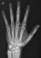 Left hand by dorsoplantar projection
 -
 Lateral projection
 -
 Oblique projection


- Fingers - DP and Lateral
- Thumb - AP and Lateral
- Femur - AP and Lateral
- Knee - AP and Lateral. Intra Condular projections on request
- Patella - Skyline projection
-
 Right knee, anteroposterior
 -
 Right knee, lateral
 -
 Patella, (slightly skew) skyline


- Tibia and Fibula - AP and Lateral
- Ankle - AP/Mortice and Lateral
-
 Ankle - frontal
 -
 15 degrees internal rotation
 -
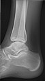 Lateral (this one a bit suboptimal by not seeing straight through the ankle joint)
 -
 Lateral oblique (to visualize the posterior border of the tibia)


- Calcaneum - Axial and Lateral
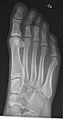
- Foot / Toes - Dorsoplantar, Oblique and Lateral.[19]
-
 Normal right foot by dorsoplantar projection
 -
 Oblique projection
 -
 Lateral projection


Certain suspected conditions require specific projections. For example, skeletal signs of rickets are seen predominantly at sites of rapid growth, including the proximal humerus, distal radius, distal femur and both the proximal and the distal tibia. Therefore, a skeletal survey for rickets can be accomplished with anteroposterior radiographs of the knees, wrists, and ankles.[20]
General disease mimics
Radiological disease mimics are visual artifacts, normal anatomic structures or harmless variants that may simulate diseases or abnormalities. In projectional radiography, general disease mimics include jewelry, clothes and skin folds. [21] In general medicine a disease mimic shows symptoms and/or signs like those of another.[22]
-
 A hip fracture (black arrow) next to a skin fold (white arrow).
 -
 Bed sheets looking like lung opacities on a chest radiograph
.jpg)

See also
- Medical imaging in pregnancy, including projectional radiography
- Radiography
- Medical imaging
- X-ray
- X-ray generator
- X-ray detector
- Radiographer
- Digital radiography
- Tomography
- Anatomical terms of location
References
- ISBN 978-1-4496-7206-5.
- ^ Bruce Blakeley, Konstantinos Spartiotis (2006). "Digital radiography for the inspection of small defects". Insight. 48 (2).
- ISBN 9783642034749.
- ^ a b c "source-to-image-receptor distance". Farlex medical dictionary, in turn citing Mosby's Medical Dictionary, 9th edition. Retrieved 2018-01-28.
- ^ DICOM (2016-11-21). "DICOM PS3.3 - Information Object Definitions - Table C.8-30. XA Positioner Module Attributes". Retrieved 2017-01-23.
- ^ M Sandborg, D R Dance, and G Alm Carlsson. "Implementation of unsharpness and noise into the model of the imaging system: Applications to chest and lumbar spine screen-film radiography" (PDF). Faculty of Health Sciences, Linköping University.
{{cite web}}: CS1 maint: multiple names: authors list (link) Report 90. Jan. 1999. ISRN: LIU-RAD-R-090 - ISBN 9780702045387.
- ^ "source-object distance". thefreedictionary.com.
- ISBN 9781437727708.)
{{cite book}}: CS1 maint: multiple names: authors list (link - ISBN 978-0-323-06611-2.)
{{cite book}}: CS1 maint: multiple names: authors list (link - ^ Advances in kilovoltage x-ray beam dosimetry, http://iopscience.iop.org/0031-9155/59/6/R183/article
- ^ Using Digital Chest Images to Monitor the Health of Coal Miners and Other Workers. National Institute for Occupational Safety and Health.
- ^ a b "Radiology - Acute indications". Royal Children's Hospital, Melbourne. Retrieved 2017-07-23.
- PMID 22807640.
- ^ a b c d e f g h i j k l m "Radiographic Standard Operating Protocols" (PDF). HEFT Radiology Directorate. Heart of England NHS Foundation Trust. 2015. Retrieved 27 January 2016.
- ^ a b "Radiation Dose in X-Ray and CT Exams". radiologyinfo.org by the Radiological Society of North America. Retrieved 2017-08-10. (CC-BY-2.0)
- ^ PMID 17713757.
- ^ Wijnbladh, H (1933). "Zur Röntgendiagnose von Schulterluxationen" [For X-ray diagnosis of shoulder dislocations]. Chirurg (in German). 5: 702.
- ^ Henry R Guly. "Foot Injuries". Royal College of Emergency Medicine. Retrieved 2017-07-28. Published: 23/12/2013. Review Date: 23/12/2017
- PMID 12853662.
- ISBN 9781907816062.)
{{cite book}}: CS1 maint: multiple names: authors list (link - ^ "mimic". TheFreeDictionary.com. Retrieved 2022-06-10.
External links
| X-ray/ radiography |
| ||||||||||||
|---|---|---|---|---|---|---|---|---|---|---|---|---|---|
| MRI | |||||||||||||
| Ultrasound | |||||||||||||
| Radionuclide |
| ||||||||||||
| Optical/Laser | |||||||||||||
| Thermography | |||||||||||||
| Target conditions |
| ||||||||||||